
Install Instructions


Control Panel and Wiring
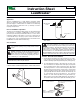
Press the tabs on the side of the control panel and pull apart
to separate the front panel from the back panel.
Using the hardware provided mount the back of the control
panel in a location close enough to the water heater so that the
both the actuator and sensor wiring can be connected to the
control panel.
I
f using batteries install into the battery holder. Be sure to
insert each battery in the correct orientation as indicated in the
battery holder. If electrical power is being used the power cord
may also be connected. LeakBreaker can be powered by bat-
teries, power supply or both.
Assemble the front on the control panel to the back of the panel.
With screws on the sensor quick connect facing toward the
back of the controller, plug the sensor wiring into the control
panel port marked sensor. Place the sensor on the floor, at the
base of the water heater, making sure it is located where water
is likely to flow. If the water heater is in a pan place the sensor
inside of the pan.
If the sensor is installed in a metal pan or on a damp surface
insert the 4 feet provided into the 4 holes on the corners of the
sensor. If additional sensors were purchased locate them in
different areas around the water heater.
With the screws on the actuator quick connect facing toward
the back of the controller, plug the acuator wiring into the con-
trol panel port marked valve.
Two (2) sets of dry contacts are provided, each set includes
normally open and normally closed connections. They can be
used to send a signal to any device requiring an open or close
signal, such as a security system.
Testing Your Installation
Press the open button on the front panel to open the valve,
watch the indicator on the top of the valve to make sure the
valve rotates to the open position, press the close button to
close the valve and watch the indicator on the top of the valve
to make sure the valve rotates to the closed position.
Close any open fixtures and open any shut-off valves that
were closed during the installation the valve. Make sure there
are no leaks.
With the valve in the open position place the sensor in water.
The valve should close, the LED should flash red and the audi-
ble alarm should sound. Once the valve closes press the mute
button to silence the alarm.
To reset the LeakBreaker completely dry off the sensor and
then press the open button.
Congratulations on the successful installation of your
LeakBreaker!
C
L
O
S
E
O
P
E
N
NO
TE
: Wh
en
attach
in
g
th
e wires
to
th
e actu
ato
r qu
i
ck co
n
-
n
ect th
e bl
ack wi
re mu
s
t match
u
p to
th
e "
B
"
o
n
th
e co
n
tro
l
an
d th
e red wi
re mu
s
t match
u
p to
th
e "
R
"
o
n
th
e co
n
tro
l.
The
Le
a
k
B
r
e
a
k
e
r wi
l
l
not
func
t
i
on c
orr
e
c
tl
y i
f i
t
i
s not
wi
r
e
d c
orr
e
c
tl
y.
NOTE: If using multiple sensors break off the tab at the end
(as shown in Note Fig. 5b) on all sensors except for the last
one in the chain. Never remove the tab when using a single
sensor or for the last sensor in the chain. See multiple sen-
sor wiring diagram for wiring
1.
1.
2.
3.
5a.
4.
Press Open
Press Close
5.
1.
2.
3.
4.
5.
5a.
6.
1.
2.
3.
4.
5b.
Mutiple Sensor Wiring
S1 S2 S3
●●●
●●●