
Wiring Guide


100
Instruction Sheet
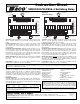
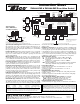
SR501-EXP-4 Switching Relay
POWER
ZONE 1
LED
INDICATORS
FUSE
6 AMP
FUSE
6 AMP
SR 501-EXP-4
POWER
CONTROLS
SLAVE
PRIORITY ON
RESET
PRIMARY PUMP ON
POST PURGE ON
PRIORITY PROTECT ON
PUMP EXERCISE ON
30 SEC/2 WK
MASTER
OFF
OFF
OFF
OFF
OFF
NORMAL
4 MIN/24 HOUR
ACCESSORY
PORT
120 VAC
INPUT
CIRCULATOR
HN/O N H
120 VAC
CIRCULATOR
PRIMARY
OUTPUT
N/C
INPUT
120 VAC
PRIMARY
CIRCULATOR
(OPTIONAL)
TO: "TT" on Boiler Aquastat
THERMOSTAT
END
SWITCH
RESET
OVERRIDE
THERMOSTATEXPANSION
X
W
R
X1A2CB
TO: DHW Aquastat if PC700
Boiler Reset is installed.
(See Page 2.)
T
24 VOLTS AC ONLY
C
SINGLE ZONE
EXPANDABLE SWITCHING RELAY
Operation: When the thermostat calls for heat, the circulating pump
is energized and the isolated end switch (X and X) will start the boiler.
Priority Operation: When the priority dip switch is set to ON and the
zone is actuated, all other connected zoning panels will stop operation
until the zone is satisfied. When the priority dip switch is set to OFF
and the zone is actuated, all other connected zoning panels will oper-
ate independently.
Mode Operation: When the mode dip switch is set to NORMAL, the end
switch relay will be energized if any zone is in operation. When the mode
dip switch is set to RESET, the end switch relay will only be energized
through the operation of a plug-in reset control or closure of Priority Input.
Primary Pump Operation: When the dip switch is set to OFF, the pri-
mary circulating pump output will not energize when zone calls for
heat. When the dip switch is set to ON, the primary circulating pump
output will energize when zone calls for heat.
Post Purge Operation: When the dip switch is set to ON, the circula-
tion pump output will stay energized for 2 minutes after its thermostat
or aquastat is satisfied, but not operate the boiler.
Priority Protection Operation: When the dip switch is set to ON and
the zone (priority) on master zone panel calls for heat continuously for
more than one hour, then power is returned to the space heating zones
allowing all the zones to function independently. Once the zone (pri-
ority) on master zone panel is satisfied, the control’s auto-reset is acti-
vated and the zone is again allowed to have priority for up to one hour.
Pump Exercise Operation: When the dip switch is set to ON, the solid
state timer cycles all the circulating pumps that are attached to the
Expandable Switching Relay at the selected time interval. The time
interval can be set for the pumps to run for either 30 seconds every 2
weeks or for 4 minutes every 24 hours.
End Switch: The switch closes when the thermostat calls for heat and
the mode switch is set to NORMAL. The end switch also closes when
the mode switch is set to RESET and a PC Series boiler reset power con-
trol is calling for heat.
Expansion Connections: Set the expansion switch to MASTER on the
switching relay that has the designated priority zone or is utilizing the
PC Series plug-in option. Set all other daisy chained controls to SLAVE.
Using thermostat wire (18-22 gauge) connect between terminals A, B,
C on the master control to the corresponding A, B, C on the SLAVE
control(s). Controls may be daisy chained up to 20 zoning panels using
any combination of -EXP controls (120 zones if all are 6 zone panels).
Thermostat Input (24 vac):
R Hot side of transformer. Connect to R on thermostat.
W Switched R signal from thermostat. Connect to W on thermostat.
C Common side of transformer. Connect to COM on
thermostat (optional).
120 VAC Connections (N is Neutral, H is Hot):
Power Input Connect 120 Volt AC power.
Primary Primary Pump (optional)
N/O Zone Circulator Zone
N/C Zone Normally closed terminal for the Circulator Zone.
Will deactivate on a thermostat call.
N Connect to pump neutral leads.
External Diagnostics: Externally visible lights show full functionality of the
switching relay. The green light should always be on, indicating that power is
connected. When the thermostat calls for heat, both the appropriate circulator
and red indicating light are energized.
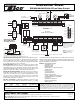
WARNING: Wiring connections must be made in accordance with all applicable electrical codes. Use copper wire only. 120 VAC wiring must have
a minimum temperature rating of 75°C. Failure to follow this instruction can result in personal injury or death and/or property damage. 12-18 gauge
wire recommended for 120 VAC connections, 14-22 gauge wire for thermostat connections, and 14-22 gauge wire for 24 VAC source connections.
Wiring Diagram:
Features:
Front External Indicator Lights
Ideal for Retrofitting
Primary Circulator Output
Simplified Wiring
Add-On Power Controls
Sealed Relays
Compact Design
Fuse Protected
100% Factory Tested
Isolated End Switch
UL Approved
Expandable to 20 Zoning Panels
(120 zones if all are 6 zone
panels)
Contractor Friendly PC Board
Layout
Universal Thermostat
Compatibility
24 volt Power Input or Output
Terminal
Extended 3 Year Warranty
Made in the USA
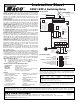
SW1
SLAVE
ZONE PRIORITY ON
RESET
PRIMARY PUMP FUNCTION ON
POST PURGE ON
PRIORITY PROTECTION ON
PUMP EXERCISE ON
30 SEC/2 WK
MASTER
OFF
NORMAL
OFF
OFF
OFF
OFF
4 MIN/24 HOUR
Dip Switch Settings:
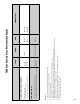
Specifications:
PRODUCT NUMBER INPUT MAXIMUM TYPE 1 ENCLOSURE
NUMBER OF ZONES VOLTAGE COMBINED LOAD WIDTH HEIGHT DEPTH
SR501-EXP-4 1 120/60/1 VAC 12 amps 4
7
/8"6
5
/8"2
3
/8"
All circulator relay connections, including ZC/ZR, are rated
1
/3 hp (6 FLA, 36 LRA) at 120 VAC.
The end switch connection is rated 24 VAC, 1 amp.
The thermostat connection supplies a 24 VAC class 2 output.
This device complies with part 15 of the FCC Rules. Operation is subject to the fol-
lowing two conditions: (1) This device may not cause harmful interference, and (2)
this device must accept any interference received, including interference that may
cause undesired operation.
For more wiring diagrams, visit www.taco-hvac.com.
Do it Once. Do it Right.
®
TACO, INC., 1160 Cranston Street, Cranston, RI 02920 Telephone: (401) 942-8000 FAX: (401) 942-2360.
TACO (Canada), Ltd., 8450 Lawson Road, Unit #3, Milton, Ontario L9T 0J8. Telephone: 905/564-9422. FAX: 905/564-9436.
Visit our web site at: http://www.taco-hvac.com
Printed in USA
Copyright 2010
TACO, Inc.