
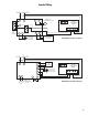
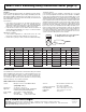
Wiring Guide

97
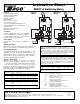
SR501-OR-4 Switching Relay Instruction Sheet (page 3)
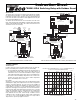
Step Two:
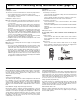
Installing the Control:
The enclosure is to be mounted flush onto a wall or any ridge surface.
• The mounting holes in the enclosure accept #6 screws.
• Line voltage to enter from bottom of control and low voltage to
enter from top of control.
Installing the Outdoor Sensor:
Note: The temperature sensor (thermistor) is built into the enclosure.
• Use one round or pan head screw to attach the base of the sen-
sor to the wall.
• The sensor is wall mounted and the wiring enters through the
bottom of the enclosure. The hole for the cable entry must face
downward in order to prevent water from entering and filling the
enclosure.
• The sensor should be mounted on a wall which best represents
the heat load on the building (i.e. a northern wall for most build-
ings and a southern facing wall for buildings with large south
facing glass areas). The sensor should not be installed near heat
sources such as ventilation or window openings.
• The sensor should be installed at an elevation above the ground
that will prevent accidental damage or tampering.
• Install the Outdoor Sensor and run the wiring back to the control
mounting location.
Installing the Boiler Sensor:
Note: This sensor is designed to mount on a pipe or in a temperature
immersion well.
• The sensor can be strapped directly to the pipe using the cable
tie provided. Insulation should be placed around the sensor to
reduce the effect of air currents on the sensor measurement.
• The Boiler Sensor should be placed downstream of a pump or
after an elbow or similar fitting. This is especially important if
large diameter pipes are used because the thermal stratification
within the pipe can result in erroneous sensor readings. Proper
sensor location requires that the fluid is thoroughly mixed within
the pipe before it reaches the sensor.
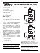
Step Three:
Wiring to the Zone Control:
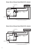
Line Voltage Connections –
Connect 120VAC incoming line voltage; Hot to the H terminal and
Neutral to the N terminal.
Connect 120VAC circulator; HOT lead of circulator to Zone H ter-
minal and Neutral lead of circulator to Zone N terminal.
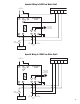
Low Voltage Connections –
Connect thermostat or zone control end switch to the R and W
thermostat terminals.
Connect the DHW aquastat to the R and W DHW override terminals
(optional).
Connect boiler’s T and T terminal to the X and X boiler end switch
terminals.
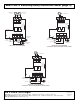
Wiring the Sensors:
Do not apply power to these terminals as this will damage the
control.
Outdoor Sensor
Connect the two wires from the Outdoor Sensor to the Outdoor
Sensor terminals. The Outdoor Sensor measures the outdoor air
temperature.
Boiler Sensor
Connect the two wires from the Boiler Sensor to the Supply
Sensor terminals. The Boiler Sensor measures the supply water
temperature going from the boiler to the system.
SETTINGS:
Before adjusting the settings, read through the sequence of operation
to ensure that you understand how the control operates. The follow-
ing page describes how to program these settings into the control
once it has been powered up.
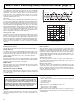
Step Four:
Outdoor Design Temperature:
The Outdoor Design setting is the outdoor temperature used in the heat
loss calculation. It is set to the typical coldest outdoor temperature.
Using a small screwdriver adjust the rest ratio knob to appropriate
Outdoor Design Temperature. When set to OFF, the boiler temperature
will not be reset and boiler will fire to high limit when there is a call for
heat.
Boiler Minimum Supply Temperature (Dip Switch #1):
Most boilers require a minimum operating temperature to prevent
corrosion from flue gas condensation. The minimum boiler dip switch
should be set to ON (140°F) supply water temperature so boiler can
operate without causing the boiler flue gases to condense. Consult
the boiler manufacturer for recommended minimum boiler supply
temperatures. The dip switch can also be set to OFF (70°F) when
condensation is not a concern.
Differential (Dip Switch #2):
The differential adjustment sets how far the actual boiler supply water
temperature may deviate from the desired temperature before the
boiler is turned on or off. This is a function of the water content of the
boiler and the flow rate through the system pump relative to the heat
output of the boiler. The differential can be set by dip switch #2, set
to OFF for 10°F (6°C) or set to ON for 20°F (12°C).
Pump Operation (Dip Switch #3):
The pump operation is controlled by dip switch #3. When the dip
switch is set to ON, the pump output will energize when thermostat
or DHW calls for heat. When set to OFF, the pump will only come on
when the thermostat calls for heat not the DHW.
Warm Weather Shut Down:
When the outdoor temperature rises above the 70°F (21°C), the con-
trol turns off the boiler. This function only applies for space heating
and not DHW operation.