
SR504-EXP Switching Relay Instruction Manual

120 VAC INPUT
TO: "TT" ON BOILER
PRIMARY CIRCULATOR
(OPTIONAL)
TO: "TT" ON BOILER WITH
DHW "TT" INPUT
FOUR ZONE
EXPANDABLE
SWITCHING RELAY
POWER
CONTROLS
120 VAC CIRCULATORS
ZC
INPUT
120 VAC
ZONE 1
ZONE 2 ZONE 3 ZONE 4
ZONE1
ZONE2
ZONE3
THERMOSTATS
SR 504-EXP-4
FUSE
6 AMP
FUSE
6 AMP
FUSE
6 AMP
FUSE
6 AMP
FUSE
6 AMP
FUSE
6 AMP
NET
EXPANSIONMAIN PRIORITY
XX
XX
AB
CRW
CRW
CRW
CRW
C
12
END SWITCH THERMOSTATS (24 VAC)
PRIORITY
N/C
PRIMARY
120 VAC
ZR
H H N H N H NH NH NH NH NH
SLAVE
PRIORITY ON
RESET
PRIMARY PUMP ON
POST PURGE ON
PRIORITY PROTECT ON
PUMP EXERCISE ON
30 SEC/2 WK
MASTER
OFF
OFF
OFF
OFF
OFF
NORMAL
LOW LIMIT (ZC) ON OFF
4 MIN/24 HOUR
ZONE4 ZONE4
PRIORITY
ACCESSORY
PORT
ZONE 2
POWER
ZONE 1
ZONE 3
ZONE 4
LED
INDICATORS
120 VAC INPUT
FOUR ZONE
EXPANDABLE
SWITCHING RELAY
POWER
CONTROLS
120 VAC CIRCULATORS
ZC
INPUT
120 VAC
ZONE 1
ZONE 2 ZONE 3 ZONE 4
ZONE1
ZONE2
ZONE3
THERMOSTATS
SR 504-EXP-4
FUSE
6 AMP
FUSE
6 AMP
FUSE
6 AMP
FUSE
6 AMP
FUSE
6 AMP
FUSE
6 AMP
NET
EXPANSIONMAIN PRIORITY
XX
XX
AB
CRW
CRW
CRW
CRW
C
12
END SWITCH THERMOSTATS (24 VAC)
PRIORITY
N/C
PRIMARY
120 VAC
ZR
H H N H N H NH NH NH NH NH
SLAVE
PRIORITY ON
RESET
PRIMARY PUMP ON
POST PURGE ON
PRIORITY PROTECT ON
PUMP EXERCISE ON
30 SEC/2 WK
MASTER
OFF
OFF
OFF
OFF
OFF
NORMAL
LOW LIMIT (ZC) ON OFF
4 MIN/24 HOUR
ZONE4 ZONE4
PRIORITY
ACCESSORY
PORT
ZONE 2
POWER
ZONE 1
ZONE 3
ZONE 4
LED
INDICATORS
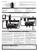
TO: "ZC" ON BOILER
TO: "ZR" ON BOILER
Priority Operation: When the priority dip switch is set to ON and the
priority zone is actuated, all other zones will stop operation until pri-
ority zone is satisfied. When not switched to priority, all zones will
operate independently.
Mode Operation: When the dip switch is set to NORMAL, the end
switch relay will be energized if any zone is in operation. When the switch
is set to RESET, the end switch relay will only be energized if the priority
zone is in operation, or through the operation of a plug-in reset control.
Primary Pump Operation: When the dip switch is set to OFF, the pri-
mary circulating pump output will energize when any zone calls for heat,
except the priority zone. When the dip switch is set to ON, the prima-
ry circulating pump output will energize when any zone calls for heat.
Post Purge Operation: When the dip switch is set to ON, the priori-
ty zone output will stay energized for 2 minutes after its thermostat or
aquastat is satisfied, but not operate the boiler.
Priority Protection Operation: When the dip switch is set to ON, and
if the priority zone calls continuously for more than one hour, power
is returned to all the other zones, allowing each zone to function inde-
pendently. Once the priority zone is satisfied, the control's auto-reset is
activated and the priority zone is again allowed to have priority for up
to one hour starting from when it calls next.
Pump Exercise Operation: When the dip switch is set to ON, the solid
state timer cycles all the circulating pumps that are attached to the
Expandable Switching Relay at the selected time interval. The time
interval can be set for the pumps to run for either 30 seconds every 2
weeks or for 4 minutes every 24 hours.
Low Limit (ZC) Operation: When the dip switch is set to ON and the
boiler drops below the set low limit (terminal ZC connected to boiler),
all zone circulating pumps will stop. When the boiler rises above the
set low limit, the zone circulating pumps are allowed to operate.
End Switches (Dry Contacts): The main end switch closes when any
zone thermostat calls for heat and the mode switch is set to NORMAL.
The main end switch also closes when the mode switch is set to RESET
and a PC Series boiler reset power control is calling for heat. The priori-
ty end switch closes only when the priority zone thermostat or aquastat
is calling for heat.
Expansion Connections: Set the expansion switch to MASTER on the
switching relay that has the designated priority zone or is utilizing the
PC Series plug-in option. Set all other daisy chained controls to SLAVE.
Using thermostat wire (18-22 gauge) connect between terminals A, B,
C on the master control to the corresponding A, B, C on the SLAVE
control(s). Controls may be daisy chained up to 20 zoning panels using
any combination of -EXP controls (120 zones if all are 6 zone panels).
Thermostat Input (24 vac):
R Hot side of transformer. Connect to R on thermostat.
W Switched R signal from thermostat. Connect to W on thermostat.
C Common side of transformer. Connect to COM on
thermostat (optional).
NET Network terminals 1 & 2 are tied together for wiring convenience
when using communicating style thermostats (optional).
120 VAC Connections (N is Neutral, H is Hot):
Power Input Connect 120 Volt AC power
Primary Primary Pump (optional)
Zone 1-3 Circulator Zones
Priority Zone 4 Priority Zone (if enabled) or Zone 4
N/C Zone 4 Normally closed terminals for the Priority Zone.
Will deactivate on a Priority Zone call.
Cold Start Boiler
Application
Tankless Coil Boiler
Application
(Alternative Wiring)
Instruction Sheet
SR504-EXP-4 Switching Relay
102-389
SUPERSEDES: New EFFECTIVE: May 1, 2010
Plant ID# 9300-2874
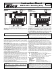
For Both Cold Start Boiler Application and Tankless Coil Boiler Application (Alternative Wiring)
For Cold Start Boiler Application
Operation: When any thermostat calls for heat, the appropriate circu-
lating pump is energized and the isolated end switch (X and X) will
start the boiler.
For Tankless Coil Boiler Application (Alternative Wiring)
Operation: When any thermostat calls for heat, the boiler will be enabled
and appropriate circulating pump is energized when the boiler tempera-
ture is above the set low limit and low limit (ZC) dip switch is set to on.
ZC and ZR Terminals: Connect terminal ZC to ZC terminal on the aqua-
stat control. Connect ZR to ZR terminal on the aquastat control. Confirm
polarity is consistent between boiler aquastat and switching relay.
WARNING: When using Alternative Wiring diagram, wiring instruc-
tions must be followed so power originates from the boiler aquastat.
Failure to follow these wiring instructions may result in a secondary
source of power being connected to the boiler that may activate it
under certain circumstances, causing injury or death.
Specifications:
PRODUCT NUMBER INPUT MAXIMUM TYPE 1 ENCLOSURE
NUMBER OF ZONES VOLTAGE COMBINED LOAD WIDTH HEIGHT DEPTH
SR504-EXP-4 4 with Priority 120/60/1 VAC 20 amps 10
3
/4"7" 2
3
/4"
All circulator relay connections, including ZC/ZR, are rated
1
/3 hp (6 FLA, 36 LRA) at 120 VAC.
End switch connections are rated 24 VAC, 1 amp.
All thermostat connections supply a 24 VAC class 2 output.
For more wiring diagrams, visit www.taco-hvac.com.
WARNING: Wiring connections must be made in accordance with all
applicable electrical codes. Use copper wire only. 120 VAC wiring must have
a minimum temperature rating of 75°C. Failure to follow this instruction
can result in personal injury or death and/or property damage. 12-18 gauge
wire recommended for 120 VAC connections, 14-22 gauge wire for ther-
mostat connections, and 14-22 gauge wire for 24 VAC source connections.