
Wiring Guide
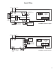


93
Instruction Sheet
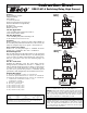
SR501-HC-4 Switching Relay, High Current
Features:
External Indicator Lights
Simplified Wiring
Sealed Relays
100% Factory Tested
Contractor Friendly PC Board Layout
Universal Thermostat Compatibility
UL Approved
Extended 3 Year Warranty
Made in the USA
120 VAC Application:
1 zone switching relay with boiler enable or
2 zone without boiler enable.
240 VAC Application:
1 zone switching relay when switching both
of the circulator hot leads (L1 & L2).
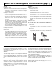
Operation:
Connect a thermostat to the R & W1 and/or W2 terminals on
the switching relay. When the thermostat(s) call for heat, the
relays are energized and power is given to the circulator(s).
Zone Control Power Input:
Connect 120 volt AC power input to terminals N and H.
Neutral wire to terminal N. Hot wire to terminal H.
External Diagnostics:
The external lights show full functionality of the switching
relay. The green light should always be on, indicating that
power is connected. When either thermostat calls for heat,
both the appropriate relay and red indicating light are
energized.
The Taco Connection:
Combine the reliability of the Taco Zone Valves, Priority
Zoning Circulators, Thermostats, and the “00” family of cir-
culators with the advanced features of the Taco Zone Controls
to achieve total system integration. No matter the applica-
tion, Taco now provides the products to maximize system
performance while simplifying both installation and service.
Terminal Description:
R Hot side of transformer. Connect to R on thermostat.
W1 Switched R signal from thermostat #1. Connect to W on thermostat.
W2 Switched R signal from thermostat #2. Connect to W on thermostat.
C Common side of transformer. Connect to COM
on thermostat (optional).
N Neutral wire of power input.
H Hot wire of power input.
X1 Dry contacts for relay 1 (W1).
X1 Dry contacts for relay 1 (W1).
X2 Dry contacts for relay 2 (W2).
X2 Dry contacts for relay 2 (W2).
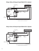
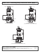
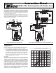
Alternative
Wiring
ONE ZONE HC
SWITCHING RELAY
SR 501-HC-4
LED
INDICATORS
R
W1
24 VAC THERMOSTAT
W2
COM
24
VAC
TTT
NH
X1
RELAY 2RELAY 1
120 VAC
INPUT
120 VAC
CIRCULATOR
X1
X2
X2
N
ZR
ZC
H
POWER INPUT
(120 VAC)
POWER
RELAY 1
RELAY 2
ONE ZONE HC
SWITCHING RELAY
SR 501-HC-4
LED
INDICATORS
R
W1
24 VAC THERMOSTAT
W2
COM
24
VAC
TTT
NH
X1
RELAY 2RELAY 1
120 VAC
INPUT
POWER
INPUT
(120 VAC)
120 VAC
CIRCULATOR
X1
X2
X2
N
H
BOILER
CONTROL
POWER
RELAY 1
RELAY 2
NOTE: When using Alternative Wiring diagram, the boiler operating
control’s ZC terminal will see the load of the circulator(s).
WARNING: When using Alternative Wiring diagram, wiring instruc-
tions must be followed so power originates from the boiler aquastat.
Failure to follow these wiring instructions may result in a secondary
source of power being connected to the boiler that may activate it
under certain circumstances, causing injury or death.
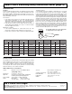
Specifications:
PRODUCT NUMBER INPUT TYPE 1 ENCLOSURE
NUMBER OF ZONES VOLTAGE WIDTH HEIGHT DEPTH
SR501-HC-4 1 or 2 120/60/1 VAC, 0.84 MA 4
7
/
8
"6
5
/
8
"2
3
/
8
"
RELAY RATING:
1
/
3
HP (13.8 FLA, 82.8 LRA at 120 VAC) (6.9 FLA, 41.4 LRA at 240 VAC)
The thermostat connection supplies a 24 VAC class 2 output.
WARNING: Wiring connections must be made in accordance with all
applicable electrical codes. Use copper wire only. Failure to follow this
instruction can result in personal injury or death and/or property
damage. 12-18 gauge wire recommended for 120/240 VAC connec-
tions, 14-22 gauge wire for thermostat connections, and 14-22 gauge
wire for 24 VAC source connections.
Typical
Wiring