
Install Instructions

Application:
The Geo-Sentry
®
Zone Valve provides on-off control and is avail-
able in normally open or normally closed configurations. It is espe-
cially suited for use in either open or closed loop geothermal sys-
tems with water source heat pumps.
Ease of Installation / Operation:
The Geo-Sentry
®
is the most technologically advanced zone valve
ever made. It’s also simple to install and operate. The valve can be
installed in any direction, in any orientation except for chilled water
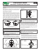
installations (see Figure B). We then went a step further, allowing the
actuator to be mounted to the valve body in either direction (see
Figure A). Snap-in quick connects on the back of the valve make for
a simple, secure and fast wiring hook-up. A green LED light shows
full functionality of the valve’s operation and thermostat status.
Under a no power situation the manual override button located on
the top of the valve allows the ball to be rotated up to 90° and is also
marked with a slot to indicate the position of the valve.
2-Way Valve Installation:
1. On hot water applications, the valve body may be installed in any
orientation. On chilled water installations, do not install with the
actuator beyond 85° from the topmost position (see Figure B).
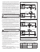
2. Before mounting the body, refer to Figure C for any clearance
requirements.
3. Use of a solder with a melting point below 600°F is recommend-
ed. Do not overheat! Make sure the ball valve is in the FULL
OPEN position during soldering. Direct flame tip away from the
center of the valve. Cool valve quickly with a wet cloth.
4. Solder build-up on the ball valve may prevent proper opening
and closing of the valve. Actuate the actuator once or twice and
make sure the valve rotates fully.
5. Valve body can be submerged for leak testing before the actu-
ator is attached.
Actuator Installation / Wiring:
1. Actuator Removal: Remove the valve actuator prior to soldering
by pushing in and holding the release clip at the front of the
actuator and lifting upward approximately
3
⁄
4
" (see Figure D).
2. To re-assemble the actuator to the valve body: Position actuator
such that the “D” shaped valve stem aligns properly with the “D”
shaped actuator drive cavity. (Note: The “D” shaped stem
design allows for correct insertion every time.) Next, slide the
Instruction Sheet
Geo-Sentry
®
Geothermal Zone Valve
102-479
SUPERSEDES: November 1, 2013 EFFECTIVE: October 19, 2017
Plant ID# 001-4131
Two Position Head Placement.
Universal Body Placement.
May be installed in any position, any orientation.
AAB B
Figure A
1
3
⁄
8
" CLEARANCE
3
⁄
4
" CLEARANCE
W
A
L
L
Figure C
NOTE: Some power robbing thermostats require the use of
a resistor (always use the resistor provided by the thermo-
stat manufacturer with the Zone Sentry). Consult the ther-
mostat instructions for the resistor installation.
Permitted Angle of Installation on Chilled Water Applications
85°
85°
Figure B
LOCKING
POST
Step 1:
Push in and hold release clip
at the front of the actuator.
Step 2:
Move actuator upward
approximately 3⁄4" to
disengage Locking Posts.
Figure D: Actuator
Removal
CAUTION: Sand or other contaminants can damage
the valves internal components and cause it to fail
prematurely. Precautions must be taken to prevent
contaminants from damaging the valve.
CAUTION: Actuator must be removed from the
valve body before soldering (see Figure D). Ball
valve must be in the full open position before sol-
dering. Valve shipped in the closed position.
NOTE: Threaded valves (2-way and 3-way) should be
installed using proper plumbing techniques for NPT threads.