
Install Instructions

Application:
Taco Zone Sentry Zone Valves provide on-off, normally open or
normally closed control in both open and closed hydronic systems.
The Taco Zone Sentry valves can be used in a wide variety of
applications, specifically designed for use in heating systems and
in chilled water systems where condensation is present. It is pri-
marily used in baseboard, fan coils, radiators, convectors, air han-
dlers, heat pumps and radiant applications. Refer to the Product
Specifications section for choosing the correct valve model for
your application.
Ease of Installation / Operation:
The Zone Sentry is the most technologically advanced zone valve
ever made. It’s also simple to install and operate. The valve can be
installed in any direction, in any orientation except for chilled water
installations (see Figure B). We then went a step further, allowing
the actuator to be mounted to the valve body in either direction
(see Figure A), great for those tight baseboard jobs. Snap-in quick
connects on the back of the valve make for a simple, secure and
fast wiring hook-up. A green LED light shows full functionality of
the valve’s operation and thermostat status. Under a no power sit-
uation the manual override button located on the top of the valve
allows the ball to be rotated up to 90° and is also marked with a
slot to indicate the position of the valve.
Valve Installation:
Inverted Flare Notes:
1. The ability to reuse inverted flare valves and/or fittings has limita-
tions, at some point the joint will no longer seal.
2. The valve and fittings should not be supporting any pipe loads.
1. On hot water applications, the valve body may be installed in any
orientation. On chilled water installations, do not install with the
actuator beyond 85° from the topmost installation (see Figure B).
2. Before mounting the body, refer to Figure C for any clearance
requirements.
3. Use of a solder with a melting point below 600°F is recommend-
ed. Do not overheat! Make sure the ball valve is in the FULL
OPEN position during soldering. Direct flame tip away from the
center of the valve. Cool valve quickly with a wet cloth.
4. Solder build-up on the ball valve may prevent proper opening
and closing of the valve. Actuate the actuator once or twice and
make sure the valve rotates fully.
5. Valve body can be submerged for leak testing before the actu-
ator is attached.
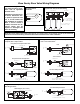
Actuator Installation / Wiring:
1. Actuator Removal: Remove the valve actuator prior to soldering
by pushing in and holding the release clip at the front of the
actuator and lifting upward approximately
3
⁄
4
" (see Figure D).
2. To re-assemble the actuator to the valve body: Position actuator
such that the “D” shaped valve stem aligns properly with the “D”
shaped actuator drive cavity. (Note: The “D” shaped stem
design allows for correct insertion every time.) Next, slide the
valve stem into the actuator cavity, push in and hold the release
clip until the actuator slips over the valve locking posts (see
Figure D). Once the actuator is flush to the valve body, let go of
the release clip. Using very little force, try to take the actuator
off of the valve body without using the release clip. Both locking
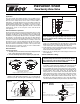
Instruction Sheet
Zone Sentry Zone Valve
102-410
SUPERSEDES: August 1, 2014 EFFECTIVE: November 1, 2014
Plant ID# 001-3944
CAUTION: Actuator must be removed from the valve body
before soldering (see Figure D). Ball valve must be in the
full open position before soldering. Valve shipped in the
closed position.
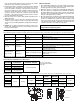
Two Position Head Placement.
Universal Body Placement.
May be installed in any position, any orientation.
AAB B
Figure A
1
3
⁄
8
" CLEARANCE
3
⁄
4
" CLEARANCE
W
A
L
L
Figure C
NOTE: Some power robbing thermostats require the use of
a resistor (always use the resistor provided by the thermo-
stat manufacturer with the Zone Sentry). Consult the ther-
mostat instructions for the resistor installation.
Permitted Angle of Installation on Chilled Water Applications
85°
85°
Figure B
LOCKING
POST
Step 1:
Push in and hold release clip
at the front of the actuator.
Step 2:
Move actuator upward
approximately 3⁄4" to
disengage Locking Posts.
Figure D: Actuator
Removal