
Install Instructions

posts should be firmly attached to the actuator. If the actuator
slides up the stem, repeat the assembly process.
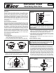
3. Changing the actuator orientation: The actuator may be attached
to the valve body in either direction (see Figure A). In order to
reverse the actuator orientation on the valve body, see the actu-
ator removal instructions in Step 1 with the following exceptions.
Instead of moving the actuator the full
3
⁄
4
", move it just high
enough to clear the locking posts, rotate the actuator 180° and
reinstall it on the locking post by following the previous instruc-
tions for reassembling the actuator.
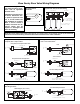
4. Wire the actuator in accordance with system requirements (see
Wiring Diagrams).
5. The plug-in quick connects can be disconnected from the valve
actuator for ease of wiring. Insert the corresponding wire into the
quick connects (see Wiring Diagrams) and tighten by turning the
screw.
6. Caution: Do not jumper power/motor (24 VAC) connection ter-
minals, even temporarily. This may cause damage to the ther-
mostat’s heat anticipator.
Mode of Operation:
1. Upon initial field installation the capacitor requires a full charge,
up to 35 seconds, before the valve starts to turn. Charging time
will vary (typically less) during normal operation.
2. When the capacitor is charging the green LED light will FLASH.
3. Once the capacitor is charged, the green LED will stop flashing
but remain ON. At this point the valve’s actuator will rotate the
ball valve. The green LED will remain ON as long as the ther-
mostat is calling (the unit is powered).
4. Once the thermostat is satisfied the green LED will turn OFF and
the valve will rotate 90° into its normal position or non-powered
position. For example: If the actuator is an NC (normally closed)
version, the actuator would open the valve when the thermostat
calls. Once the thermostat is satisfied the actuator would then
rotate the valve 90° to its normally closed position.
A
D
C
F
E
B
G
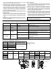
Dimensions (for reference purposes): English dimensions are in inches. Metric dimensions are in millimeters. Metric data is presented in ( ).
* At 4' per second (max.
recommended residential
flow rate).
WARNING: Do not use zone valves on indirect water
heaters without a tempering device.
1
3
⁄
8
" CLEARANCE
3
⁄
4
" CLEARANCE
W
A
L
L
VALVE SIZE
C
v
(Kv)/Ft.
of PIPE EQUIV.*
CLOSE-OFF PSI (kPa)
1
⁄2” 4.9 (4.3) / 9.5
0-125 psi (0-862 kPa)
3
⁄4” 10.3 (8.9) / 8.4
1” 8.9 (7.7) / 47.4
Inverted Flare
3
⁄4” sweat fitting
3.5 (3.0) / 72.9
VALVE SIZE A B C D
E
(Sweat)
E
(Threaded)
F G
1
⁄2”
3 (76.2) 2
3
⁄8 (60.3)
4
1
⁄8 (104.8)
3
1
⁄16 (77.8)
3
1
⁄8 (79.4)
3
3
⁄4 (95.3)
1
9
⁄16 (39.7)
2
5
⁄16 (58.7)
3
⁄4”
3
1
⁄8 (79.4)
3
5
⁄16 (84.1)
1” 3
7
⁄8 (98.4) 3
7
⁄8 (98.4) 1
7
⁄9 (47.6)
Inverted Flare
3
⁄4” sweat fitting
3
1
⁄2 (99.1) 3
1
⁄16 (77.8) 7
3
⁄8 (187.3)**
3
1
⁄
2 (88.9) 1
3
⁄4 (44.5) 3
5
⁄16 (84.1)
Multi-status LED and Troubleshooting:
This troubleshooting table is intended as a helpful guide and is not all inclusive. There could be other causes and solutions for a non-functioning product.
LED STATUS INDICATES POSSIBLE CAUSE POSSIBLE SOLUTION
Not Illuminated Power off
No call
No power
Verify there is a call.
Check for voltage at the actuator.
Steady blink (once per
second)
Charging
Solid Power on
Slow blink (once every
5 seconds)
Excessive
charging time
Not enough VA
Reset the actuator (see note).
Use a larger VA transformer or add an additional transformer.
Too many valves per transformer
Reduce the number of valves.
Use a different thermostat.
Double blink (twice
every 5 seconds)
Excessive
opening time
Obstruction in valve
Buildup of contamination in valve
Reset the actuator (see note).
Remove obstruction.
Clean the valve and/or system.
Replace valve.
Failed actuator Replace Actuator.
NOTE: Reset the actuator by removing power for 5 seconds and then restoring power.
Flow Coefficients and Maximum Close-Off Pressure:
** E Sweat dimension includes inverted flare fittings.
E Threaded dimension is less fittings.