
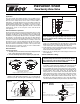
Install Instructions

W
ARNING: Wiring connec-
tions must be made in accor-
dance with all applicable
e
lectrical codes.
CAUTION: To prevent electri-
cal shock, disconnect elec-
tric power to system at main
fuse or circuit breaker box
until installation is complete.
When a service switch is
installed, more than one dis-
connect switch may be
required to deenergize this
device for servicing.
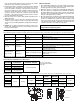
Zone Sentry Zone Valve Wiring Diagrams
L
ED
M
otor
Circuit
End Switch
c
w
/y
Simplified Internal
Schematic:
Thermostats
Transform er
T
o “T” Term inals
o
n Boiler Control
T
ransform er Relay
T
T
Up to 12 Valves per
40va Transformer
L
1 (Hot)
L
2
24 v
End Sw itch
Rh/Rc
w/y
Rh/Rc
w/y
Rh/Rc
w/y
w/y
c
End Sw itch
w/y
c
End Sw itch
w/y
c
L1 (Hot)
L2
Thermostat
To “T” Term inals
Motor
End Switch
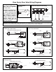
Honeywell, Erie and Sparco Wire Leads
Wiring a Taco Zone Sentry Zone Valve to Replace a
Honeywell, Erie or Sparco Valve:
Honeywell and Erie Terminal Block
L1 (Hot)
L2
Thermostat
To “T” Term inals
M otor
End Switch
TH
TR
TR
TH
ES
ES
L1 (Hot)
L2
Thermostat
To “T” Term inals on Boiler
Control Transformer Relay
Taco Zone Sentry Zone Valve
c
End Switch
w/y
Wiring a Taco Zone Sentry Zone Valve to Replace a
Flair or Taco 3-Wire Valve:
Taco Zone Sentry Zone Valve
Taco 570 Series
L1 (Hot)
L2
Thermostat
To “T” Term inals
Motor
End Switch
1
2
3
Flair
L1 (Hot)
L2
Thermostat
To “T” Term inals
Motor
End Switch
1
2
3
45
L1 (Hot)
L2
Thermostat
To “T” Term inals on Boiler
Control Transformer Relay
c
End Switch
w/y
Wiring a Taco Zone Sentry Zone Valve to Replace a
White Rodgers Valve:
L1 (Hot)
L2
To “T” Term inals on Boiler
Control Transformer Relay
Taco Zone Sentry Zone Valve
46
5
L1 (Hot)
L2
To “T” Term inals
Motor
End Switch
6
4
White-Rodgers (1311 or 1321)
4
56
Thermostat
5
2
3
1
Thermostat
c
End Switch
w/y
Typical Zone Sentry Zone Valve Wiring:
NOTE: Some power robbing thermostats require the use of a resistor (always use the resistor provided by the thermostat
manufacturer with the Zone Sentry). Consult the thermostat instructions for the resistor installation.