
Install Instructions

WARNING: Wiring connec-
tions must be made in accor-
dance with all applicable
electrical codes.
CAUTION: To prevent electri-
c
al shock, disconnect elec-
tric power to system at main
fuse or circuit breaker box
until installation is complete.
When a service switch is
installed, more than one dis-
connect switch may be
required to deenergize this
device for servicing.
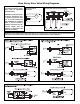
Zone Sentry Zone Valve Wiring Diagrams
L
ED
M
otor
Circuit
End Switch
c
w
/y
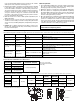
Simplified Internal
Schematic:
Typical Zone Sentry Zone Valve Wiring:
NOTE: Some power robbing thermostats require the use of a resistor (always use the resistor provided by the thermostat
manufacturer with the Zone Sentry). Consult the thermostat instructions for the resistor installation.