
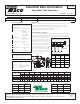
Submittal Sheet

101-140
Zone Sentry
®
Ball Zone Valve
Effective: September 1, 2014 Supersedes: June 26, 2013
Submittal Data Information
Job: Engineer:
Contractor:
Rep:
ITEM NO. MODEL NO.
Do your best work.
®
TACO INC., 1160 Cranston Street, Cranston, RI 02920 Telephone: (401) 942-8000 Fax: 942-2360
TACO (Canada), Ltd., 6180 Ordan Drive, Mississauga, Ontario L5T 2B3 Telephone: (905) 564-9422 Fax: (905) 564-9436
Visit our website at: www.taco-hvac.com
Printed in USA
Copyright 2015
TACO, Inc.
Taco Inc., 1160 Cranston, Cranston, RI 02920 / (401) 942-8000 / Fax (401) 942-2360
Taco (Canada) Ltd., 8450 Lawson Road, Unit #3, Milton, Ontario L9T 0J8 / (905) 564-9422 / Fax (905) 564-9436
www.taco-hvac.com
Submittal Data # 101-140 Eective: 09/01/14
Supersedes: 06/26/13
Submittal Data Information
Zone Sentry
®
Ball Valve Zone Valve
Application:
Taco Zone Sentry® Zone Valves provide on-off, normally open or normally closed
control in both open and closed hydronic systems. The valves can be used in
a wide variety of heating and non condensing cooling applications, primarily
designed for use with baseboad, fan coils, radiators, convectors,
air handlers, heat pumps and radiant applications.
Ease of Installation / Operation:
The Taco Zone
Sentry
is the most technologically advanced zone valve ever made.
It’s also simple to install and operate. The valve can be installed in any direction, in
any orientation. We then went a step further, allowing the operator to be mounted
to the 2-way valve body in either direc-
tion, great for those tight baseboard jobs.
Snap-in quick connects on the back of
the valve make for a simple, secure and
fast wiring hook-up. A green LED light
shows full functionality of the valve’s
operation and thermostat status. Under
a no power situation the manual override
button located on the top of the valve
allows the ball to be rotated up to 90°
and is also marked with a slot to indicate
the position of the valve.
Thermostats
Transformer
To “T” Terminals
on Boiler Control
Transformer Relay
T
T
Up to 12 Valves per
40va Transformer
L1 (Hot)
L2
24 v
End S witch
Rh/Rc
w/y
Rh/Rc
w/y
Rh/Rc
w/y
w/y
c
End S witch
w/y
c
End S witch
w/y
c
Typical Zone Sentry Zone Valve Wiring:
Product Specifications
Max. Operating Pressure ..300 PSI (2100 kPa)
Max. Shutoff Pressure .........125 PSI (875 kPa)
Max. Ambient Temp. ...........135˚F
Fluid Temp. Range ................20-240˚F (7˚-115˚C)
Service .........................................Water or
..................................................................Water/Glycol up
..................................................................to 50% Glycol
.....................................................................Close Systems
Ball Rotation Speed ................(90˚ turn),
.............................................................Approx. 5 seconds
Electrical Rating ........................24 VAC, 60Hz
.............................................................0.48 Amps
Power Consumption..............11.4 W, 0.48 Amps
Power Consumption..............1.44W, 0.06 Amps
Heat Anticipator Setting .....0.5 Amps
End Switch Rating ...................1 Amp @ 24 VAC
Materials of Construction, Actuator:
Body .........High Performance Engineered Polymer
Gears ........High Performance Internally Lubricated
......................Engineered Polymer
Materials of Construction, Valve:
Body ............................ Forged Brass
Stem ............................Brass
Press Ring ................ Brass
Ball................................. Brass (Chrome Plated)
Seat .............................. Modified Teflon®
O-Rings ..................... EPDM
Zone Sentry
Dimensions:
FOR REFERENCE PURPOSES
A
D
C
F
E
B
G
H
Valve
Size
A B C D
E
(Sweat)
E (Threaded) F G
H
(3-way)
in. mm in. mm in. mm in. mm in. mm in. mm in. mm in. mm in. mm
1/2” 3” 76.2 2.375” 60.3 4.125” 104.7 3.06” 77.72 3.125” 79.3 4.750” 120.6 1.562” 39.7 2.312” 58.7 5.06" 128.5
3/4” 3” 76.2 2.375” 60.3 4.125” 104.7 3.12” 79.25 3.125” 79.3 3.312” 84.1 1.562” 39.7 2.312” 58.7 5.37" 136.4
1” 3” 76.2 2.375” 60.3 4.125” 104.7 3.12” 79.25 3.875” 98.4 3.875” 98.4 1.875” 47.6 2.312” 58.7 5.50" 139.7
Inverted Flare
3/4”sweat fitting
3” 76.2 2.375” 60.3 3.5” 99.1 3.06” 77.72 7.375” * 187.33 3.5” ** 88.9 1.75” 44.5 3.312” 84.1 N/A N/A
(after charge time)
(Charging)
(Power On)
(Open System —
Option Available)
Valve
Size
Close-O
Pressure
(kPa)
3-WAY
Cv (Kv) / Ft. of
Pipe Equiv. †
2-WAY
Cv (Kv) / Ft. of
Pipe Equiv. †
1/2” 4.9 (4.3) / 9.5
0-125 psi
(0-862 kPa)
1.5 (1.3) / 111
3/4” 10.3 (8.9) / 8.4
0-125 psi
(0-862 kPa)
3.3 (2.8) / 82
1” 8.9 (7.7) / 47.4
0-125 psi
(0-862 kPa)
3.0 (2.6) / 411
Inverted Flare
3/4" sweat
tting
4.4 (3.8) / 46.2
0-125 psi
(0-862 kPa)
N/A
† At 4’ per second (Max. recommended residential ow rate).
NPT Models 2-Way
Sweat
Models
Z050T2 1/2" 2-way Z050C2
Z075T2 3/4" 2 way Z075C2
Z100T2 1" 2-way Z100C2
NPT Models 3-Way
Sweat
Models
Z050T3 1/2" 3-way Z050C3
Z075T3 3/4" 3-way Z075C3
Z100T3 1" 3-way Z100C3
Consult factory for additional model numbers.
* Includes inverted flare fitting ** Less fittings