Owner’s Manual M/S - 2150 X True Digital Amplifier
Blank Page
WARNING M/S-2150 X WARNING TO REDUCE THE RISK OF FIRE OR ELECTRIC SHOCK, DO NOT EXPOSE THIS APPLIANCE TO RAIN OR MOISTURE. CAUTION RISK OF ELECTRIC SHOCK DO NOT OPEN CAUTION: TO REDUCE THE RISK OF ELECTRICAL SHOCK, DO NOT REMOVE COVER. NO USER-SERVICEABLE PARTS INSIDE. REFER SERVICING TO QUALIFIED PERSONNEL.
Safety M/S-2150 X Important Safety Instructions 1. 2. 3. 4. 5. Cleaning and Maintenance 1. 2. “Note” symbol Read these instructions entirely before installing or operating this equipment. Keep these instructions. Heed all warnings. Do not use this equipment near water or allow it to become wet. Do not block any ventilation openings. Install in accordance with the manufacturer’s instructions. CAUTION 6.
Acknowledgments M/S-2150 X Acknowledgments © 2003 Tact Audio Corporation. All rights reserved. No part of this document may be reproduced or transmitted in any form or by any means, electronic, mechanical, photocopying or other wise, without the prior written consent of Tact Audio Corporation. TACT® is a registered trade mark of Tact Audio Corporation. DYNAMIC ROOM CORRECTION® is a registered trade mark of Tact Audio Corporation.
M/S-2150 X Table of contents Safety instructions 4 Acknowledgments/Registration 5 Unpacking the M/S-2150 X 7 Introduction 6 Tact Audio CAUTION 8 Dynamic Room Cirrection 9 M/S-2150 X Connections 12 Front Panel Controls 18 Remote Control 19 Front Panel Display Main screen MAIN menu Saving Menu Settings DELAY menu LEVEL menu POL menu InOut menu RCS menu MSR menu CRO menu PAREQ menu MODE menu OPT menu DISPL menu REM menu COMM menu ADDR menu ADC menu LOCK menu GAIN menu TRIG menu 21 21 22 22
Unpacking M/S-2150 X Unpacking the M/S-2150 X Carefully remove the M/S-2150X and accessory kit from the carton and check for shipping damage. Contact both the shipper and TacT Audio immediately if the unit shows any sign of damage from rough handling. All TacT Audio equipment is carefully inspected before leaving our factory. KEEP SHIPPING CARTON AND PACKING MATERIALS for future use or in the unlikely event that the unit needs servicing.
Introduction M/S-2150 X Introduction Congratulations on your purchase of your M/S 2150X. You have now acquired the most advanced stereo amplifier ever developed! How does it work? The digital input is taken to the central processor where it is reformatted into a pulse width modulated signal of extreme precision. The pulse rate is measured at precisely 384,000 pulses per second. Each pulse can have 256 different widths, CAUTION with the narrowest pulse being a mere 10 nanoseconds wide.
DRC M/S-2150 X Dynamic Room Correction M/S-2150 X is designed to support full range and subwoofer Dynamic Room Correction (DRC). All software necessary to perform this task is built into each M/S-2150 X. However M/S-2150 X does not have built in microphone preamp and it does require an external digital microphone preamp such as BOZ RCS-16M. With RCS-16M up to 16 channels of DRC can be performed. Each M/S-2150 X channel can be configured as main (full range) or subwoofer channel.
DRC M/S-2150 X Equal loudness curves represent the SPL that different frequencies need to have in order to be perceived as two tones of equal loudness. For example, a 200 Hz tone at SPL of 50 dB will have the same perceived loudness as a 1000 Hz tone at SPL of 40 dB. In this case both 200 Hz and 1000 Hz tones have a loudness of 40 phons, and they both belong to the 40 phons equal loudness curve.
How does it work? Dynamic Room Correction (DRC) offers a very sophisticated way of handling a multi target curve approach to solving equal loudness curve problem. The system is based on one reference target curve and eight additional target curves called dynamic target curves. The reference target curve is used to perform basic reference room correction.
Connections M/S-2150 X M/S-2150 X Connections Digital input The M/S-2150 X amplifier has 5 digital inputs: - three RCA (S/PDIF) ( D1, D2, D3) - one AES/EBU (XLR) (D4) - one TosLink (S/PDIF) (D5) CAUTION All of the digital inputs support PCM audio data with sampling rates from 32kHz to 96kHz /16-24 bits, however, the AES/EBU and RCA/coaxial inputs support up to 192kHz.
Connections M/S-2150 X Digital output The M/S 2150 X amplifier has a digital pass through. The digital input signal is passed to the digital output without processing or volume control. The sampling rate is the native sampling frequency of the input. NOTE: that this output is not active when analog input is selected.
Connections Trigger outputs M/S-2150 X The M/S-2150 X has a trigger “IN” and “OUT” to provide on and standby control from a trigger device and to pass the trigger signal to another device. Trigger Connectors CAUTION AC mains input Connect the M/S-2150 X to the AC mains wall socket. CAUTION: Use the supplied IEC mains cable, or a 3-prong grounded cable only. AC Main Input Speaker output (normal operation) The M/S-2150 X amplifier has one pair of high quality speaker terminals.
Connections M/S-2150 X Speaker output (Biamped operation) If you are using two or more M/S-2150 X amplifiers, and your speakers allow for multiamping, you can configure the system to run in biamped, tri-amped or multi-amp mode. This type of setup allows for one amplifier channel to drive a specific driver or frequency region. The most commonly used setup is biamped (two channels to each speaker: high and low frequency range).
Connections Vertical Biamping M/S-2150 X LEFT SPEAKER CAUTION HIGH HIGH LOW LOW RIGHT SPEAKER LEFT SPEAKER HIGH + 16 Tact Audio RIGHT SPEAKER - HIGH + - LOW LOW + + - -
Connections M/S-2150 X Biamping - continued When two or more M/S-2150 X amplifiers are configured in a bi-/tri-amped setup, both the signal and the RS232 TacT System Bus must be daisy chained between the amplifiers. The same signal flow is applicable for both horizontal and vertical bi-amping. From source Digital signal (coax/SPDIF) usually CD player output. From RCS2.0S, RCS2.
Front Panel M/S-2150 X Front Panel Controls The front panel controls on the 2150 X amplifier will allow you to control all of the amplifiers main features. All secondary options are controlled with menus using the remote control or the supplied software. The exclusive “TacT wheel” is the master volume control.
Remote Control M/S-2150 X Remote Control The remote control is used to access the front panel display controls and menus.
Remote Control M/S-2150 X 1 - STANDBY The STANDBY button will turn the M/S 2150 X “ON” or it will place it into “STANDBY” mode. When in standby mode, the unit is placed into a low power “idiling” state. The standby button is also used to save changes that were made in the menu editing parameters. By placing the unit into standby the current settings are saved. CAUTION 2 - DIGITAL The DIGITAL button will scroll sequentially, allowing the selection of one of the 5 digital inputs.
Main Screen M/S-2150 X Front Panel Display Main screen When the M/S-2150 X amplifier is turned ON and the system loading sequence has completed, the amplifier will display the main screen. Main Screen 1 CRO Mode 2 CRO:>BP * EQ: BP * -17.9 dB Fs= 44.1 3 MODE menu option is set to CRO mode. M/ S-2150 X operates in crossover mode. CRO menu option is enabled and RCS, MSR, DRC and DOPT menu options are disabled. 4 RCS or RCS-SUB Mode RCS:>BP * EQ: BP * -17.9 dB Fs= 44.
Main Menu MAIN menu M/S-2150 X The Main menu of the M/S 2150 X has three pages of general menu selections. Main Menu <- CRO PAREQ MODE DELAY LEVEL POLCAUTION OPT DISPL REM -> InOut RCS MSR-> <- COMM ADDR ADC <- VER MIC DRC LOCK GAIN TRIG -> DOPT The remote control is needed to enter the amplifiers Menu selection pages. Press the MENU button to enter the amplifiers menu section. Use the LEFT and RIGHT buttons to highlight an option with the selection cursor.
Main Menu Options M/S-2150 X DELAY menu The Delay menu controls the system’s time alignment. The system’s time alignment can be adjusted by changing the delay time for the left and right outputs independently. . Delay Menu LEFT RIGHT 0.00 0.00 msec 1 1 - Left and Right channel delay time settings. Use LEFT and RIGHT navigational buttons to highlight an option and use UP and Down buttons to change its value . The maximum delay time value that can be set is 31.95 msec (0.03195 seconds).
Main Menu Options M/S-2150 X POL menu (Polarity) Use this menu to set channel polarity. Each channel can be set to + (non inverted) or - (inverted) polarity. Polarity Menu: LEFT RIGHT + CAUTION + 1 2 1 - Left channel polarity setting. 2 - Right channel polarity setting. To highlight an option use the LEFT or RIGHT buttons. To selected highlighted option use the UP , DOWN of ENTER buttons. A unique channel polarity can be assigned to each crossover and correction preset.
Main Menu Options RCS Menu M/S-2150 X Use this menu to select one of the correction presets. M/S-2150 X offers 9 correction presets as well as bypass. This screen is enabled only if RCS or RCS-SUB mode is selected (see MODE menu). Correction names are user programmable from M/S-2150 X windows based application program.. RCS Menu : 2 RCS 1: Corr #1 1: Corr #1 1 1 - Correction preset selections. 2 - Active correction preset. Use the “UP” and “DOWN” buttons to scroll through all possible options.
Main Menu Options CRO menu M/S-2150 X The CRO menu is used to select CRO presets and edit their values. You can select BUTT (Butterworth filter type) or BUTTSQ (Butterworth squared filter type) and edit HP, LP or BP filters. This menu is only accessible when CRO mode is selected (see MODE menu option). CRO Menu : CRO: Bypass 1: Preset #1 To enable this screen set MODE CAUTION menu screen to CRO option. EDIT Use LEFT and RIGHT buttons to place screen cursor over Preset nad EDIT options.
Main Menu Options PAREQ M/S-2150 X Parametric EQ menu is used to apply up to twelve bands of parametric equalization per output channel. PAREQ Menu 4 PAREQ PRESET: BP PR: 1 LEFT RIGHT 1 2 3 Use LEFT or RIGHT buttons to move the screen cursor to fields 1,2 and 3. 1 - When the screen cursor is in this field use UP/DOWN buttons to scroll through all possible ParEq presets. To select/engage displayed ParEq preset press ENTER button. Selected ParEq preset will be displayed in field 4.
ParEq Menu Options PAREQ Editing M/S-2150 X To edit ParEq parameters in ParEq MENU screen select LEFT to edit left channel parameters or RIGHT to edit right channel parameters. Depending on the selection one of the following screens will be displayed: RIGHT Edit Menu LEFT Edit Menu LF LEV FR OCT CAUTIONRF LEV FR OCT 1 -12.2 1400 0.29 1 -12.2 1400 0.29 1 2 3 4 1 2 3 4 Use LEFT or RIGHT buttons to move the screen cursor to fields 1,2,3 and 4.
Main Menu Options Mode menu M/S-2150 X The Mode menu allows for selection of M/S-2150 X operating mode. If RCS mode is not used the unit should always be set to CRO mode. 2 CURRENT MODE: CRO CRO RCS RCS-SUB 1 1 - Display Mode selections. 2 - Active Mode setting. Use the LEFT and RIGHT buttons to highlight the desired option and select it by pressing the ENTER button.
Main Menu Options M/S-2150 X DISPL menu (Display) The display menu controls the display Time-Out feature. This option is used to turn the front panel display ON or OFF. When this option is set to ON the front panel timer will turn the front display off if the front panel has not been accessed for more than 10 seconds. To wake the display, simply turn the wheel or push any button either the front panel or the remote control.
Main Menu Options M/S-2150 X COMM menu (Communication) Use this menu to enable MASTER or NORMAL communication mode. In the MASTER mode M/S-2150 X will send master volume and mute changes as well as standby/ON status to all M/S-2150 X units connected to AUX RS232 port. Note that only one unit can be configured as MASTER and all others must be configured as NORMAL units - slaves. Communication Menu BAUD RATE: 57600 CONTROL: NORMAL 1 1 - Master/Normal control setting.
Main Menu Options M/S-2150 X ADC menu (ADC module optional) The M/S-2150 X may be equipped with an optional state of the are Analog to Digital Converter. To further enhance the converter’s performance, the system offers two selectable gain values for the ADC input stage. These two values may be assigned to each input independently. ADC Menu 2 3 CAUTION GAIN IN 2: HIGH LOW HIGH 1 1 - Assignable gain values. 2 - Input channel currently selected. 3 - Active gain setting for selected input channel.
Main Menu Options M/S-2150 X GAIN menu The gain menu is designed to select the amount of digital amplification applied to audio signal. Digital gain can be set from 0 to 18.0 dB in increments of 0.1 dB. These feature should be used in cases with low audio signal levels - CD’s that are not fully modulated (do not cover full signal range). Increasing the amount of digital gain does not increase M/S-2150 X output power.
M/S-2150 X Software Tact M/S-2150 X Software The M/S-2150 X is more than just an amplifier. With powerful features such as level balancing, time alignment, and assignable electronic crossovers, you can customize and build the amplifier system that you need, whether your system is biamped, triamped or more. When in CRO mode M/S-2150 X does not require computer interface. However, when in RCS mode M/S-2150 X requires computer interface via RS232 communication port.
M/S-2150 X Software Connect your M/S-2150 X to your Computer Your M/S-2150 X must be connected to your computers serial port in order for it to communicate with your computer when you run the M/S-2150 X software. Please follow the steps below to connect your M/S-2150 X to your computer. 1 - Connect the RS 232 Input jack on the back of the M/S-2150 X to your computers serial port using the supplied cables and adapters. Your computer must have a standard RS 232 serial port with a DB 9 connector.
Specifications M/S-2150 X Specifications CAUTION Power (RMS. per channel) 8 ohm 2 x 150W Power (RMS. per channel) 4 ohm 2 x 300W Output current (peak, per channel) >50 A Signal-to-noise ratio ( A-weighted) >110dB Dynamic range (20 Hz - 20 kHz) >130dB THD+N (all power levels 20Hz-20kHz) <0.01% Digital resolution 16-24 bit Linearity (-120dB) +- 0,2dB Dimensions (WxHxD) 450x140x420 mm 17.7x5.5x16.5 in.
Crossover Package M/S-2150 X M/S-2150 X Crossover Package Tact Audio Inc. 201 Gates Road Little Ferry, NJ 07643 USA V1.
Crossover Package M/S-2150 X INTRODUCTION M/S-2150 X crossover filter (CRO) package is designed to support computer less digital filter design using only front panel display CRO menu option. The crossover filter design is based on infinite impulse response (IIR) CAUTION implementation. All crossover filters are implemented as digital IIR Butterworth filters.
Crossover Package M/S-2150 X Since M/S-2150 X is a two-channel power amplifier a crossover filter can be assigned to each output channel. Both Left and Right channels support LP, HP and BP filters with a cutoff frequency set to any value between 10 and 24000 Hz with 1 Hz resolution. Filter order, which determines the filter slope, can be set to any value from 1 to 12 with increments of 1 for each channel independently.
Editing CRO Preset To edit CRO preset #1 scroll through field 2 until Preset #1 is displayed. Place cursor over EDIT (field 3) and then press ENTER button. The following screen will be displayed: EDIT 2 1 Menu L: BUTT CAUTION R: BUTT 3 EDIT EDIT 4 Field 1 and 3 display left and right channel crossover filter assignment. To change this field place the cursor next to it and press ENTER button. This field can display BYPASS, BUTT and BUTTSQ options.
Crossover Package M/S-2150 X Editing Filters Continued 3. Use this field to select high-pass filter order for selected filter type. If BUTT filter was selected this field could be set to any number between 1 and 12 (first and twelfth order) in increments of 1. If BUTTSQ was selected this field could be set to any number between 1 and 6. In BUTTSQ case two sections of Butterworth filter are cascaded to form Butterworth squared filter.
Crossover Package M/S-2150 X Measurement Sample 1 CAUTION Fig 1 Left/Right channel frequency response. Output signal level at –6 dB which is equivalent to 37.5 W into 8 Ohms or 70 W into 4 Ohms. Left channel set to BUTT low-pass filter with FL set to 100 Hz and LO set from 1 to 10. Right channel set to BUTT high-pass filter with FH set to 100 Hz and HO set from 1 to 10. EDIT menu setup for Fig.
Crossover Package M/S-2150 X Measurement Sample 2 Fig 2 Left/Right channel frequency response. Output signal level at –6 dB which is equivalent to 37.5 W into 8 Ohms or 70 W into 4 Ohms. Left channel set to BUTT low-pass filter with FL set to 1000 Hz and LO set from 1 to 10. Right channel set to BUTT high-pass filter with FH set to 1000 Hz and HO set from 1 to 10. EDIT menu setup for Fig.
Crossover Package M/S-2150 X Measurement Sample 3 +0 -5 -10 CAUTION -15 -20 -25 d B r -30 -35 -40 -45 -50 -55 -60 -65 -70 6 10 20 50 100 200 500 Hz Fig 3 Low-pass and High-pass crossover filters with cutoff frequency of 10 Hz and filter order from 1 to 10. Output signal level at –6 dB equivalent to 37.5 W into 8 Ohms or 70 W into 4 Ohms.
Crossover Package M/S-2150 X Measurement Sample 4 +0 -5 -10 -15 -20 -25 d B r A -30 -35 -40 -45 -50 -55 -60 -65 -70 20 50 100 200 500 1k 2k 5k 10k 20k Hz Fig 4 Low-pass and High-pass crossover filters with cutoff frequency of 100 Hz and filter order from 1 to 10. Output signal level at –6 dB equivalent to 37.5 W into 8 Ohms or 70 W into 4 Ohms.
Crossover Package M/S-2150 X Measurement Sample 5 CAUTION Fig 5 Low-pass and High-pass crossover filters with cutoff frequency of 1000 Hz and filter order from 1 to 10. Output signal level at –6 dB equivalent to 37.5 W into 8 Ohms or 70 W into 4 Ohms.
Crossover Package M/S-2150 X Measurement Sample 6 +0 -5 -10 -15 -20 -25 d B r -30 -35 -40 -45 -50 -55 -60 -65 -70 100 200 500 1k 2k 5k 10k 20k Hz Fig 6 Low-pass and High-pass crossover filters with cutoff frequency of 10 KHz and filter order from 1 to 10. Output signal level at –6 dB equivalent to 37.5 W into 8 Ohms or 70 W into 4 Ohms.
Crossover Package M/S-2150 X Subwoofer COR Application Most high-end stereo configurations consist of two main loudspeakers covering frequencies form fc up to 20,000 Hz, and two subwoofers covering bottom end of the spectrum below fc. In most applications fc is set to around 100 Hz but it is not unusual for fc to extend all the way to around 300 Hz. Properly integrating a system like this one can be quite challenging.
Crossover Package Example 1 M/S-2150 X To make sure that both amplifiers will process Left and Right channel check Amp#1 and Amp#2 InOut menu options. They should be set as follows: Amp#1 InOut menu OUTPUT: L SOURCE: L Amp#2 InOut menu R R * OUTPUT: L SOURCE: L R R * Also make sure that initially for both amplifiers DELAY and LEVEL menu options are set to as follows: Amp#1 and Amp#2 DELAY menu LEFT RIGHT 0.00 0.00 msec Amp#1 and Amp#2 DELAY menu LEFT RIGHT 0.0 0.
Crossover Package Example 1 M/S-2150 X CRO preset 2 (CRO- 2) for both amplifier is the same as preset 1 except that in preset 2 filter order for both Left and Right channel is set to 9. CRO preset 2 is shown in figure below.
Crossover Package M/S-2150 X Example 1 Fig. 7 Amp#1 and Amp#2 Left/Right channel frequency response. Output signal level at –6 dB which is equivalent to 37.5 W into 8 Ohms or 70 W into 4 Ohms. LP-2, LP-3, …,LP-10 represent Amp#2 Left/Right channel frequency response with LP-2 corresponding to CRO preset 1 (CRO –1 ) , LP-3 corresponding to CRO preset 2 (CRO –2) and the last filter LP-10 corresponds to CRO preset 9 (CRO-9).
Crossover Package Example 2 M/S-2150 X Vertical bi-amplification In this configuration M/S-2150 X amplifier labeled Amp#1 is connected to the main left and subwoofer left channel. Left channel of Amp#1 is connected to the left subwoofer and Amp#1 right channel is connected to the left main loudspeaker. M/ S-2150 X amplifier labeled Amp#2 is connected to the main right and subwoofer right channels.
Crossover Package M/S-2150 X Example 2 Left channel Amp#1 EDIT menu L: LO HO FL-Hz FH-Hz LP 10 -- 100 ----- Right channel Amp#1 EDIT menu R: LO HO FL-Hz FH-Hz HP -- 10 ----- 100 Left channel Amp#2 EDIT menu Right channel Amp#2 EDIT menu L: LO HO FL-Hz FH-Hz LP 10 -- 100 ----- R: LO HO FL-Hz FH-Hz HP -- 10 ----- 100 CRO preset 2 (CRO- 2) for both amplifier is the same as preset 1 except that in preset 2 filter order for both Left and Right channel is set to 9.
Crossover Package M/S-2150 X To summarize: • • All presets for Amp#1 are set to low-pass filter for left channel and to high-pass for right channel. Left channel cutoff frequency (LF-Hz) is set to 100 Hz and right channel cutoff frequency (HF-Hz) is set to 100 Hz. Amp#2 CRO presets are identical to Amp#1 CRO presets. CAUTION NOTE: After any parameter CRO parameter in changed you must click on SEND option to send that parameter to selected amplifier.
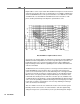
Crossover Package M/S-2150 X Example 2 Fig 8 Amp#1 and Amp#2 Left/Right channel frequency response. Output signal level at –6 dB which is equivalent to 40 W into 8 Ohms or 80 W into 4 Ohms. LP-2, LP-3, …,LP-10 represent Amp#1 and Amp#2 Left channel frequency response. HP-2, HP-3, …,HP-10 represent Amp#1 and Amp#2 Right channel frequency response LP-2 corresponds to CRO preset 1 (CRO –1 ) , LP-3 corresponds to CRO preset 2 (CRO –2) and the last filter LP-10 corresponds to CRO preset 9 (CRO-9).
Crossover Package Example 3 M/S-2150 X Two-Way Loudspeaker System There are many advantages to using bi-amplification instead of the standard configuration, where one power amplifier is used to drive one loudspeaker with two or more drivers along with passive crossover networks. In the world of high-end audio in the last few years there has been constant increase in demand for sophisticated DSP based bi-amplification solution.
Crossover Package Example 3 M/S-2150 X To summarize: • All the presets for Amp#1 are set to low-pass filter for both left and right channel with cutoff frequency (LF-Hz) of 1000 Hz and filter order (LO) going from LO=10 for preset 1 (CRO –1) to LO=1 for preset 9 (CRO-9). • All the presets for Amp#2 are set to high-pass filter for both left and right channel with cutoff frequency (HF-Hz) of 1000 Hz and filter order (HO) CAUTION going from HO=10 for preset 1 (CRO –1) to HO=1 for preset 9 (CRO-9).
Crossover Package M/S-2150 X Tact Audio 59
TacT Audio, Inc. 201 Gates Road Unit G, Little Ferry – New Jersey 07643, USA Phone: +1 201 440 9300 – Fax: +1 201 440 5580 – Email: info@tactaudio.com www.tactaudio.