SV-100-M-DVR Operations Manual TAG 22355 TAG Way Dulles, VA 20166
Operations Manual 1 Copyright © 2008 Technology Advancement Group®, Inc. (TAG®) All rights reserved. This publication and its contents are proprietary to TAG. No part of this publication may be reproduced in any form or by any means without the written permission of TAG, 22355 TAG Way, Dulles, Virginia 20166-9310. TAG has made every effort to ensure the correctness and completeness of the material in this document. TAG shall not be liable for errors contained herein.
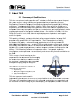
Operrations Man nual 2 Ab bout TAG G 2.1 Summarry of Quallifications s TAG hass served as s a leading provider off IT solution ns to DoD customers c o over the passt 20+ yea ars and has a long-stan nding and respected r h history of prroviding Systems Enginee ering, Electrronic Equip pment and Program P Ma anagementt support to o US Militaryy warfighters. Headq quartered in n Dulles, Viirginia, TAG G’s state-off-the-art 35,,000 sq. ft.
Operatio ons Manuall 2.2 Core Com mpetence es 2.2.1 Engineering g TAG’s engineering e methodolo ogy is built upon u Multi--Disciplinaryy Optimizattion (MDO) and rigorouss design rev views. Although PMs drive the scchedule at TAG, Engin neering leverage es Compute er-Aided De esign (CAD D) tools, Computationa al Fluid Dyn namics (CFD D) models, rapid proto otyping proccesses, and d diverse te est equipme ent and faccilities to ensure requirem ments are being b met at every step p of the dessign.
Operations Manual production/integration schedule. TAG’s floor technicians are cross-trained in multiple disciplines so they can be redistributed to any cell that encounters production bottlenecks, which ensures optimal efficiency. 2.2.3 Lifecycle Management TAG’s world-class Program Management discipline models the renowned methodologies of the Project Management Institute (PMI) to ensure successful completion of the task at hand.
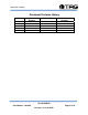
Operations Manual Document Revision History Date 08/18/2009 Version Number 1.0 Updated By Alan Huckerby Description of Changes Author SV-100-M-DVR Part Number: 1008148 Page 6 of 54 Version 1.0.
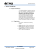
Operations Manual 3 About This Manual 3.1 Scope and Audience This Manual provides an introductory overview of the SV-100-MDVR. Designed to endure the rigors of harsh environments, products can withstand shock and vibration, high and low temperatures, and sand and dust. All of our servers are based on the latest in Intel® Core™ Duo and Pentium® M technology. Configuration options include extended memory and enhanced video optimization.
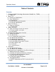
Operations Manual Table of Contents Contents 1 Copyright © 2008 Technology Advancement Group®, Inc. (TAG®) ............................ 2 1.1 Trademarks ............................................................................................................ 2 2 About TAG ................................................................................................................... 3 2.1 Summary of Qualifications ......................................................................................
Operations Manual List of Figures Figure 5-1 SV-100-M-DVR ............................................................................................ 15 Figure 5-2 SV-100-M-DVR (Front View)........................................................................ 16 Figure 5-3 SV-100 M-DVR Components and Connectors (Front View) ........................ 18 Figure 5-4 SV-100-M-DVR Components and Connectors (Rear View) ......................... 19 Figure 5-5 System Mother Board ................................
Operations Manual List of Tables Table 5-1 Mother Board Components ........................................................................... 21 SV-100-M-DVR Part Number: 1008148 Page 10 of 54 Version 1.0.
Operations Manual Chapter 1 Cautions and Warnings. Electronically distributed. Subject to user discretion when printed. SV-100-M-DVR Part Number: 1008148 Page 11 of 54 Version 1.0.
Operations Manual 4 Safety Instructions Read this manual thoroughly, paying special attention to the cautions and warnings. 4.1 Types of warnings used in this manual 4.1.1 Safety Symbols and Labels DANGER WARNING CAUTION These warnings and cautions indicate situations or practice that might result in property damage. 4.1.2 Conventions 4.1.2.1Important Messages Important messages appear where mishandling of components is possible or when work orders can be misunderstood.
Operations Manual italics. The italicized text is the warning message. 4.1.2.3Cautions Cautionary messages should also be heeded to help you reduce the chance of losing data or damaging the system. Cautions are easy to recognize. The word “caution” is written as “CAUTION,” both capitalized and bold and is followed by text in italics. The italicized text is the cautionary message. 4.1.2.4Notes Notes inform the reader of essential but noncritical information.
Operations Manual Chapter 2 SV-100-M-DVR Electronically distributed. Subject to user discretion when printed. SV-100-M-DVR Part Number: 1008148 Page 14 of 54 Version 1.0.
Operations Manual 5 SV-100-M-DVR Workstation Overview Figure 5-1 SV-100-M-DVR 5.1 Product Information The SV-100-M-DVR sets the standard for Servers with state-of-the-art technology. The newest server can stand up to the harshest environments, and is designed specifically to be fully customized to support unique, missioncritical applications. • Small Footprint Chassis, 4”H x 8”W x 8”D &7.1 lbs. Your system may contain components not described in this User Manual.
Operations Manual 5.2 SV-100-M-DVR Figure 5-2 SV-100-M-DVR (Front View) 5.2.1 SV-100-M-DVR Specifications Chassis & Power Supply • Dimensions: 4”H x 8”W x 8”D. • Weight: 7.1 lbs. • Internal Power: Built in DC power supply. • External Power: External DC adapter (90W or 120W). • Capable of sitting on a desk or mounted on a wall. (Option). System Specifications. • CPU: Intel® T7100 Core 2 Duo Processor 1.86 GHZ, 800MHz FSB. • Cache: 2MB shared L2 cache per Core.
Operations Manual • Onboard: Intel 6MA965 graphics controller with integrated Graphics Media Accelerator X3100. (VGA and DVI Connectors). • • PCI-X Video Capture Card Operating System: Choice of Windows® Vista, Windows® XP Professional or Linux. • I/O Ports: • (2) RJ-45 10/100/1000 Ethernet ports. • (10) USB 2.0 ports (6x internal; 4x external). • (2) Serial ports. • • (3) Audio ports (Mic-in, Line-out, Line-in PS/2 keyboard and mouse port. • Optional Keyboard: Mobile backlit USB keyboard.
Operations Manual Maintenance and Repair • The SV-100-M-DVR is considered a line replaceable unit (LRU) and will be maintained and spared at the LRU level. 5.3 SV-100-M-DVR Connectors Figure 5-3 SV-100 M-DVR Components and Connectors (Front View) SV-100-M-DVR Part Number: 1008148 Page 18 of 54 Version 1.0.
Operations Manual Figure 5-4 SV-100-M-DVR Components and Connectors (Rear View) 5.4 SV-100-M-DVR Components This section provides an overview of the most common components installed in the SV-100M-DVR. Information is also provided on how to identify specific components within your SV100-M-DVR. For detailed information on the specific components installed, refer the manufactures website. 5.4.
Operations Manual Figure 5-5 System Mother Board 5.4.2 System Mother Board Main Features Processor • • • • • • • Supports Intel® UFC-PGA 478 Core™ 2 Duo/Celeron® M mobile processor- Intel GME965 and ICH8M Two 200-pin SODIMM sockets support up to 4 GB dual channel DDR2 533/667 SDRAM Supports dual display for VGA, LVDS, and DVI Supports 4 serial ports and 3 SATA ports Built-in dual Gigabit Ethernet One CompactFlash Type I/II support Onboard TPM 1.2 support (optional).
Operations Manual Supported Network AGP 0 ISA 0 Mini PCI 0 PCIex1 0 PCIex16 0 PCIex4 0 LAN 2 GbE Table 5-1 Mother Board Components 5.4.3 Video Capture Card Figure 5-6 Video Capture Card SV-100-M-DVR Part Number: 1008148 Page 21 of 54 Version 1.0.
Operations Manual 5.4.4 Features: • • • • • • • • Advanced DMA for ultra-high performance (full 30 fps) Hardware audio gain control Closed Caption extraction AVI or extended AVI capture for use with the most popular 3rd party editing and streaming software applications Hardware Cropping and Bitmap Overlay PCI-X compatible Audio Loop-back Simulstream® Ready 5.4.
Operations Manual Chapter 3 Procedures. Electronically distributed. Subject to user discretion when printed. SV-100-M-DVR Part Number: 1008148 Page 23 of 54 Version 1.0.
Operations Manual 6 Procedures The procedures within this Chapter contain relevant information to ensure the SV-100-MDVR maintains its maximum performance potential. 6.1 SV-100-M-DVR Startup 1. Check to make sure that all the cables are seated and connected correctly to the back of the unit such as keyboard, mouse, monitor video cable and both power cables. 2. Connect video, touch screen USB, audio and power cables to the display CBP-19SW. 3.
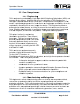
Operations Manual access the BIOS setup. When a Startup password is configured, the computer will prompt for it at every startup. The CMOS password can be reset by shortening the "CMOS restore to factory defaults jumper" or by temporarily removing the CMOS battery. 7 Identifying Server Components Using Device Manager The Device Manager is one of Windows' most useful diagnostic tools. It lets you see all of the devices attached to your computer, and which resources they are each using.
Operations Manual 2. Double-click the System icon. (Figure 7-2). Figure 7-2 System Properties 3. Click the Hardware tab, and then click the Device Manager button. (Figure 7-3). Figure 7-3 Device Manger SV-100-M-DVR Part Number: 1008148 Page 26 of 54 Version 1.0.
Operations Manual After opening Device Manager, you will see a list of all the devices Windows detected on your system. The Device Manager display is recreated each time the computer is started, or whenever a dynamic change to the computer configuration occurs, such as addition of a new device while the system is running. NOTE: To include hidden devices, on the View menu, click Show hidden devices. A check mark next to Show hidden devices indicates hidden devices are showing.
Operations Manual 7.1 Working with Device Properties To display a device's properties do the following: 1. Access the Device Manager as described in steps 1 through 3. (Figure 7-4). Figure 7-4 Device Manager SV-100-M-DVR Part Number: 1008148 Page 28 of 54 Version 1.0.
Operations Manual 2. In the Device manager dialog box (Figure4-4\), double-click the device, or select the device and then click the Properties toolbar button. (Figure 7-5). Figure 7-5 Properties Dialog Box In the device's Properties dialog box, there might be several tabs. You can view the status and configuration information, as well as the device manufacturer, device type, and location in the upper portion of the General tab.
Operations Manual Other tabs include the Driver tab, which displays the details of the driver being used. This tab also lets you update or uninstall the driver. The Resources tab displays the hardware resources being used. This tab allows you to see and resolve any conflicts caused by non-PnP devices. Along with these tabs, some devices have additional advanced settings or tabs for device-specific settings. 7.
Operations Manual 7.2.1 Using the Add New Hardware Wizard If the device is not working properly, try using the Add New Hardware Wizard. To run this wizard, do the following: 1. From the Start menu, point to Settings and then click Control Panel. (Figure 7-6). Figure 7-6 Control Panel 2. Double-click the Add Hardware icon. (Figure 7-7). SV-100-M-DVR Part Number: 1008148 Page 31 of 54 Version 1.0.
Operations Manual Figure 7-7 Add hardware Wizard 7.3 Installing Legacy Peripherals When you install what Microsoft calls a legacy peripheral, you will need to use the Add Hardware Wizard, as described to let Windows know about the new device. NOTE: The term legacy refers to anything that's no longer on the cutting edge. 7.3.1 Removing Legacy Peripherals When removing a legacy peripheral from your system, you need to let Windows know that the device is gone.
Operations Manual 2. Double-click the System icon. (Figure 7-9). Figure 7-9 System Properties 3. Click the Hardware tab. 4. Click the Device Manager button. (Figure 710). SV-100-M-DVR Part Number: 1008148 Page 33 of 54 Version 1.0.
Operations Manual Figure 7-10 Device Manager 5. Click the name of the item you have removed from your system. If you don't see the item, look for a category heading that describes the type of device you removed, and then click the plus sign to its left to display a list of items in that category. 6. From the Action menu, click Uninstall. 7. Click OK. SV-100-M-DVR Part Number: 1008148 Page 34 of 54 Version 1.0.
Operations Manual 7.4 TAG Approved BIOS The BIOS (basic input/output system) is the program stored on the CMOS that the server's microprocessor uses to get the system started after you turn it on. The BIOS also manages data flow between the computer's operating system and attached devices such as the hard disk, video adapter, keyboard, and mouse. CAUTION: The BIOS installed on your server was loaded and tested with all the devices initially installed in your system.
Operations Manual 1. Enter BIOS then Press F9. On the Setup Popup Configuration Screen menu select YES and press Enter. (Figure 7-11). Figure 7-11 Default Selection Screen 2. On the Advanced option select ACPI Configuration and Press Enter. (Figure 7-12). Figure 7-12 ACPI Configuration Screen SV-100-M-DVR Part Number: 1008148 Page 36 of 54 Version 1.0.
Operations Manual 3. On the ACPI screen drop down menu select ACPI v2.0, Press Escape to return back to the Advanced menu screen. (Figure 7-13). Figure 7-13 ACPI Option Screen. SV-100-M-DVR Part Number: 1008148 Page 37 of 54 Version 1.0.
Operations Manual 4. On the Advanced options screen, scroll down and select APM Configuration. Press Enter. (Figure 7-14). Figures 7-15, 7-16 show the various default settings. Leave on Default then press Escape to return back to the Advanced options screen. Figure 7-14 APM Configuration Screen. SV-100-M-DVR Part Number: 1008148 Page 38 of 54 Version 1.0.
Operations Manual 5. Default settings for APM Configuration, Press Escape. (Figure 7-15). Figure 7-15 APM Default Settings Screen. 6. Default settings for APM Configuration, Press Escape. (Figure 7-16). SV-100-M-DVR Part Number: 1008148 Page 39 of 54 Version 1.0.
Operations Manual Figure 7-16 APM Default Settings Screen. 7. On the Advanced options screen, scroll down and select PCIPnP. Press Enter. (Figure 718). Figures 7-19, 7-20, show the various default settings. Leave on Default then press Escape to return back to the Advanced settings Screen. (Figure 7-17). Figure 7-17 PCIPnP Screen. SV-100-M-DVR Part Number: 1008148 Page 40 of 54 Version 1.0.
Operations Manual 8. Default settings for PCIPnP Configuration, Press Escape. (Figure 7-18). Figure 7-18 PCIPnP Default Settings Screen 9. Default settings for PCIPnP Configuration, Press Escape. (Figure 7-19). SV-100-M-DVR Part Number: 1008148 Page 41 of 54 Version 1.0.
Operations Manual Figure 7-19 PCIPnP Default Settings Screen 10. On the Advanced options screen, scroll down and select Chipset. Press Enter. (Figure 720). Figures 7-21, 7-22, show the various default settings. Leave on Default then press Escape to return to the Advanced options screen. Figure 7-20 Chipset Options Screen. SV-100-M-DVR Part Number: 1008148 Page 42 of 54 Version 1.0.
Operations Manual 11. On the Advanced Chipset Settings Screen select CPU Configuration, Press Enter to see settings. (Figure 7-21). Figure 7-21 CPU Configuration Screen. 12. Default CPU Advanced Settings (Figure 722). Then press Escape to return to Advanced options screen. SV-100-M-DVR Part Number: 1008148 Page 43 of 54 Version 1.0.
Operations Manual Figure 7-22 CPU Advanced Settings Screen. 13. On the Advanced options screen, scroll down and select Video Function Configuration screen. Press Enter. (Figure 7-23). Figures 7-24, 7-25, show the various default settings. Leave on Default then press Escape to return back to the Advanced settings Screen. Figure 7-23 Video Function Configuration screen. SV-100-M-DVR Part Number: 1008148 Page 44 of 54 Version 1.0.
Operations Manual 14. On Video Configuration screen set display as required Figure 7-24). Then press Escape to return to Main BIOS screen. Figure 7-24 Display Configuration Screen. 15. On the Advanced Chipset Settings screen Scroll down to USB Configuration, Press Enter. (Figure 7-25). SV-100-M-DVR Part Number: 1008148 Page 45 of 54 Version 1.0.
Operations Manual Figure 7-25 USB Configuration Screen. 16. Default USB Functions Settings (Figure 726). Then press Escape to return to Advanced options screen. Figure 7-26 USB Functions Settings Screen. SV-100-M-DVR Part Number: 1008148 Page 46 of 54 Version 1.0.
Operations Manual 17. On the Advanced options screen, scroll down and select Onboard Devices screen. Press Enter. (Figure 7-27 and Figure 7-28 show the various default settings. Leave on Default then press Escape to return back to the Advanced settings Screen Press Enter (Figure 9-28). Figure 7-27 Onboard Devices Screen. 1. Default Onboard Devices Settings (Figure 7-28). Then press Escape to return to Advanced options screen. SV-100-M-DVR Part Number: 1008148 Page 47 of 54 Version 1.0.
Operations Manual Figure 7-28 Default Onboard Devices Settings Screen. 2. On the Advanced options screen, scroll across and select Boot tab. Press Enter. (Figure 7-29). Figure 7-30, 7-31, and 7-32 show the various default settings. Leave on Default then press Escape to return back to the Advanced settings Screen. (Figure 829). Figure 7-29 Boot Devices Screen. 3. Default Boot Devices Settings (Figure 730). Then press Escape to return to Boot options screen.
Operations Manual Figure 7-30 Boot Devices Settings Screen. 4. Default Boot Devices Settings. Then scroll down a further Boot options screen. (Figure 7-31) and (Figure 7-32). Figure 7-31 Boot Device Screen. 5. Default Boot Devices Settings (Figure 732). Then press Escape to return to Boot options screen. SV-100-M-DVR Part Number: 1008148 Page 49 of 54 Version 1.0.
Operations Manual Figure 7-32 Boot Device Screen. 6. On the Boot options screen, scroll across and select Security tab. Press Enter. Change or renew your password then Press Escape to return back to the Security settings Screen. (Figure 7.33). Figure 7-33 Password Screen. 7. On the Security options screen, scroll across and select Boot tab. Press Enter. SV-100-M-DVR Part Number: 1008148 Page 50 of 54 Version 1.0.
Operations Manual Ensure Quick Boot is Enabled (Figure 734). Figure 7-34 Boot Settings Configuration Screen. 8. On the BIOS Setup Utility screen, scroll across and select Exit tab. Press F10. (Figure 7-35). SV-100-M-DVR Part Number: 1008148 Page 51 of 54 Version 1.0.
Operations Manual Figure 7-35 Exit Option screen. SV-100-M-DVR Part Number: 1008148 Page 52 of 54 Version 1.0.
Operations Manual 9. On the Exit Options screen select OK. Then Press Enter. (Figure 7-36). Figure 7-36 Save Configurations Screen SV-100-M-DVR Part Number: 1008148 Page 53 of 54 Version 1.0.
CONTACT 7.4.2 22355 TAG Way Dulles, VA 20166 Tel: 1-800-824-8693 www.tag.com Technical Support USA 1-800-TAG-TECH Outside USA While every precaution has been taken to ensure the accuracy and completeness of this literature. TAG assumes no responsibility and disclaims and liability for damage resulting from use of this information or for any errors or omissions.