
User Manual


Library Security Pedestal 3
8/68 Revision 2.1 December 2009
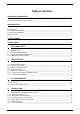
List of Figures
Figure 1: FCC maximum Power and Region settings (Uplink Data Rate) 15
Figure 2: LSP3 Clear Panel Overview 17
Figure 3: Safety Electrical Installation Using Power Cord 20
Figure 4: Clearance Distances around Pedestals 22
Figure 5: Light Barrier Orange and Green LED Lit when positioning Correct 23
Figure 6: Top view of correct L-SP3 installation and In/Out Counter Directions 24
Figure 7: People Counter View when facing light barrier and counter display 24
Figure 8: Light Beam Crossing Detection Cells & Display 24
Figure 9: Side view of correct L-SP3 installation 25
Figure 10: Pedestal Mountings 26
Figure 11: L-SP3 Clear Bottom Plastic Cover (4 screws) 26
Figure 12: Chronogram Sample (1 Master/ 4 Slaves) 29
Figure 13: 3 Pedestals Configuration Example and Token Propagation 31
Figure 14: Detailed of Wire Synchronization Assembly 32
Figure 15: PEM Connectors & Cables Location 33
Figure 16: Advanced Settings Tab Sections and Fields 34
Figure 17: Communication Configuration Tab (connected to a L-SP3) 38
Figure 18: TCP/IP Configuration Window 39
Figure 19: TCP/IP Configuration and Firmware Upgrade Tab 40
Figure 20: Pedestal Monitoring Tab 41
Figure 21: Database Window 44
Figure 22: Basic Pedestal Configuration Tab 45
Figure 23: Multi-gate configuration with two different IDs 47
Figure 24: GPIO Pulse & Pause Field 48
Figure 25: Peripherals & GPIO Green Connector Pin Out & Location 48
Figure 26: Internal Circuit of GPIO and External Supply Wiring in Output Mode 49
Figure 27: Connection of a Switch as an Input Device. 50
Figure 28: Connection of a Source and Sink Current Supply as an input Device 51
Figure 29: Advanced Pedestal Configuration Tab 52
Figure 30: Master/Slaves Synchronization Antenna Best Configuration 53
Figure 31: Asynchronous Event Notification Subfield. 54
Figure 32: People Counter & Detection Cells Location 55
Figure 33: Mains Fuses Location and Ratings 57
Figure 34: Mechanical Dimensions of Pedestal Base Fixing Plate 61
Figure 35: Outer Dimensions of LSP3 Clear Panel 62
Figure 36: Tag Orientation 63
Figure 37: Example 63
Figure 38: Test Chart 64