
Installation Manual


Power Node Radio ModuleUser's Guide
July 2015 Revision 1.1 11/17
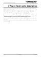
4 Power Node Radio Interface
4.1 Overview of the Radio module
The Power node radio modules has two coaxial connections, one for the Hot Spot receive RFID
signal, one for the transmit RFID signal. The three connectors are U.FL type, female, board
receptacles.
The Power node radio is also connected to a Power Node mother-board that pilots it and provides
the supply. The piloting is done through an asynchronous link (RS232 like) with a Tx and a Rx
connections.
The supply voltage is 5.5 V, the maximum current is 1.2 A. The maximum power consumption is
6.6 W.
A common connector, SAMTEC MMS-114-02F-SV, group’s commands and supply signal.
Pin 1,2 Supply ground
Pin 3,4 5.0 V supply
Pin 5 UART Rx
Pin 6 UART Tx
Pin 9 UART Ground
The commands concern the switching on-off, the output power of the module. The module sets
automatically its own gain in order to deliver the same output power from a given input range.
Tx connection
Rx connection
Supply and
control