Model #TPGAZ1559 INSTALLATION GUIDE 10’x12’ Polycarbonate Gazebo
Operation 1 (28) Hanger 36 (33) Bolt\Flat Washer M6*15 88 (35) Bolt\Flat Washer M6*38 16 (12) (12) (12) (12) Fig.1 Fig.1 (12) (33) (13) 1. Attach Post (12) to Base Plate (13) with Bolt (33). See Fig.
Operation (continued) (5b) (5a) Fig.2 Fig.2 (5b) (28) X8 (5b) (5b) (5a) (41) (9) (5a) (5b) (9) (5a) (33) 2. Insert Hanger (28) into the track of Short Right Lintel (5b). Attach Short Left Lintel (5a) and Short Right Lintel (5b) to Connector (41) with Bolt (33). At the same time, attach Connection Piece (9) to Short Lintel (5a/5b) with Bolt (33). See Fig.
Operation (continued) Fig.4 (6b) (6a) Fig.3 Fig.3 (6b) (28) X10 (6b) (6a) (41) (6b) (6a) Fig.4 (6a)(6b) (33) (9) (33) 3. Insert Hanger (28) into the track of Right Lintel (6b). Insert Connector (41) into Left Lintel (6a) and Right Lintel (6b) and fasten them with Bolt (33). At the same time, attach Connection Piece (9) to Lintel (6a/6b) with Bolt (33). See Fig.3/Fig.
Operation (continued) (6b) (5a) (6a) Fig.7 (5b) (5b) (5a) Fig.5 (12) (6a) (6b) (12) Fig.6 (12) (12) Fig.5 Fig.6 (33) (7) (6a) (35) (5a) (6b) (5b) (12) (12) Fig.7 (6a) (5b) (8) (8) (33) (33) 4. Attach Short Right Lintel (5b) and Long Left Lintel (6a) to Post (12) with Bolt (35). Repeat on each corner. See Fig.5 5. Attach Bracket (7) to Short Right Lintel (5b) and Long Left Lintel (6a) with Bolt (33). Repeat on each corner. See Fig.6 6.
Operation (continued) 2 (32) Bolt\Steel Washer M6*15 8 (33) Bolt\Flat Washer M6*15 14 (34) Bolt\Flat Washer\ Nut\ Plastic Nut Cap 40 M6*15 (2) (3) (4) Fig.9 Fig.8 (3) (11a) X20 (32) (34) (34) (2) X2 Fig.10 X20 (4) (34) X2 7. Attach Bolt (34) to Lower Central Connector (2). Note: do not over tighten. See Fig.8 8. Attach Top Connector (11a) to Long Bar (3) with Bolt (32), insert two Bolts (34) into the slot of Long Bar (3) from the other end. Repeat on each side. See Fig.9 9.
Operation (continued) Fig.12 (2) (3) Fig.11 (3) (6b) (6a) (3) (5b) Fig.12 (3) (5b) Fig.12 (5a) (6a) (6b) Fig.12 Fig.11 Fig.12 (3) (3) (34) (3) (33) (5b)/(6b) (3) (2) (11a) (3) (3) (5a)/(6a) (12) 10. Insert the Long Bar (3) with the connected small piece into Bolt (34) of Lower Central Connector (2),Tighten Bolt (34). See Fig.11 11. Attach Top Connector (11a) located below Long Bar (3) to Post (12) with Bolt (33). See Fig.
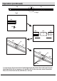
Operation (continued) (5a) Fig.14 (4) (5b) Fig.13 (4) (5b) (5a) Fig.14 Fig.13 (3) Fig.14 (3) (34) (4) (9) (2) (33) (4) (4) (3) (3) (5a) (5b) 12. Insert Short Bar (4) into Bolt (34) of Lower Central Connector (2); tighten Bolt (34). See Fig.13 13. Attach underside of Short Bar (4) to Connection Piece (9) with Bolt (33). See Fig.
Operation (continued) (2) Fig.15 (4) (4) Fig.16 Fig.16 Fig.16 Fig.15 (3) (4) (4) (3) (4) (9) (4) (4) (2) (33) (34) (3) (4) (4) (3) (6a)/(6b) 14. Insert Short Bar (4) into Bolt (34) of Lower Central Connector (2); tighten Bolt (34). See Fig.15 15. Attach underside of Short Bar (4) to Connection Piece (9) with Bolt (33). See Fig.16 Adjust the position and alignment of all ten bars (ensuring that they are vertical and parallel). At the same time, adjust the Connection Piece (9).
Operation (continued) 3 3 17 (17) 18 19 (16) (17) 1 0 2 3 17 17 9
Operation (continued) 7 10
Operation (continued) 1 2 3 18 1 11 3
Operation (continued) 4 7 12
Operation (continued) 5 13
Operation (continued) 5 20 21 See Fig.28 .See Fig.
Operation (continued) 22 23 15
Operation (continued) Fig.
Operation (continued) 26 27 When finished, adjust position of Supporting Tubes, ensuring they are vertical and parallel. Repeat on each side.
Operation (continued) 6 37 6 ( 37 ) ( ) (33) ( ) (33) 6 18 37
Operation (continued) 6 Fig.