Taisync User Manual www.taisync.
Contents 1. 2. 3. 4. Package Contents ...................................................................................... 1 Product Description ................................................................................... 3 2.1. Parameters ...................................................................................... 3 2.2. Air Unit Interfaces ......................................................................... 4 2.3. Ground Unit Interfaces ..........................................
5. 6. 7. 4.6.5. Max power ........................................................................ 30 4.6.6. Working profile ................................................................ 31 4.7. Upgrade ........................................................................................ 31 Applications............................................................................................. 32 5.1. Applications of system in detail ................................................... 32 5.2.
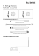
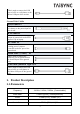
1. Package Contents Air Unit & Ground Unit Air unit antenna & feeder line × 2 (2.4G antenna for air unit) (2.4G feeder extension line for air unit) (1.4G antenna for air unit) (1.
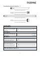
Ground unit antenna & feeder line ×2 (2.4G antenna for ground unit) (2.4G feeder line for ground unit) (1.4G antenna for ground unit) (1.4G feeder line for ground unit) Air Unit Cables Power cable x1 This is used to connect the output of a battery to the power input of the air unit. RJ45 cable x1 This is used to connect the ETH output of camera to the ETH input of the air unit. RC cable x1 This is used to connect the PPM/S.bus port of flight controller to the RC port of the air unit.
This is used to connect the USB port of a PC or a cell phone, to the Micro USB port of the air unit. Ground Unit Cables Power cable x1 This is used to connect the output of a battery to the power input of the air unit. RJ45 cable x1 This is used to connect the ETH output of ground unit to the ETH input of a pc or laptop. RC cable x1 This is used to connect the training port of a remote controller to the RC port of the ground unit.
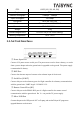
FEC LDPC (1/2, 2/3, 3/4, 5/6) Duplex TDD Downlink throughput 2.3Mbps ~ 12Mbps Uplink throughput 115.2kbps Encryption AES 128, AES 256 Interface Ethernet, Serial, PPM/S.BUS Dimension 77.8X47.3X23.5mm Weight 103g Rated voltage/current DC12V/1.2A (or 3S lithium battery) Working temperature -30°C ~55°C 2.2.Air Unit Interfaces ① ② ③ ④ ⑤ ① Power Input Port Connect 12V power source to this port.
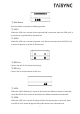
① ②③ ① Bind Button Press this button to perform the binding operation. ② LED 1 When this LED is on, it means the air-to-ground link is connected; when this LED is off, it means the air-to-ground link is disconnected. (Not available for air unit) ③ LED 2 When this LED is on, it means the ground -to-air link is connected; when this LED is off, it means the ground -to-air link is disconnected. (Not available for air unit) ① ② ① RF2 Port Connect the 2nd air unit antenna to this port.
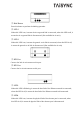
① ① Fan Ventilation Outlet Don’t block this fan ventilation outlet to ensure effective cooling. 2.3.Ground Unit Interfaces ① ② ③ ④ ⑤ ① Power Input Port Connect 12V power source to this port. The power source can be from a battery, or can be from a power adaptor when the ground unit is upgraded on the ground. The power supply recommended 3s battery. ② RJ45 Port Connect this ethernet output port to the ethernet input port of a camera using the supplied RJ45 cable.
① ②③ ① Bind Button Press this button to perform the binding operation. ② LED 1 When this LED is on, it means the air-to-ground link is connected; when this LED is off, it means the air-to-ground link is disconnected. ③ LED 2 When this LED is on, it means the ground -to-air link is connected; when this LED is off, it means the ground -to-air link is disconnected. ② ① ① RF2 Port Connect the 2nd air unit antenna to this port. ② RF1 Port Connect the 1st air unit antenna to this port.
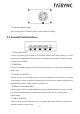
① ① Fan Ventilation Outlet Don’t block this fan ventilation outlet to ensure effective cooling. 3. Installation 3.1.Air Unit Installation 3.1.1. Attenna installation ◆ 2.4G air unit Insert the air unit antennas into the RF ports. Antenna clicks in when properly installed. ◆ 1.
Insert the air unit antennas into the RF ports with RF cables. RF cables clicks in when properly installed. Note: (1) To avoid equipment damage, install antennas before powering on the units. (2) When install air unit to drone, avoid the antennas being blocked by parts of the drone. (3) Both antennas need to be installed. (4) Ensure the antenna connector is vertical to the module when it is pushed into the RF port. (5) When uninstall the antenna, hold the connector and pull it out of the RF port.
3.1.2. Power supply Pin-out: - - + +. Insert the four-pin connector of supplied power cable to the power port of the air unit and connect the orange power connect of supplied power cable to a battery output, or the power supply port of a drone. Recommended voltage is 12V. Note: (1) To avoid equipment damage, install antennas before powering on the units. (2) Recommended rated voltage/current is DC12V/1.2A (or 3S lithium battery).
3.1.3. Connection to camera Connect the ethernet video output port to the ethernet video input port of the air unit.
3.1.4. Connection to flight controller (RC & telemetry) Insert the six-pin connector of supplied serial cable to the serial port of the air unit and connect the other end of the serial cable to the telemetry port of a flight controller. Insert the supplied RC cable to the RC port of the air unit and connect the other end of the RC cable to the PPM/S.BUS port of a flight controller.
3.2.Ground unit installation 3.2.1. Attenna installation Insert the air unit antennas into the RF ports with RF cables. RF cables clicks in when properly installed. Note: (1) To avoid equipment damage, install antennas before powering on the units. (2) When install air unit to drone, avoid the antennas being blocked by parts of the drone. (3) Both antennas need to be installed. (4) Ensure the antenna connector is vertical to the module when it is pushed into the RF port.
Insert the four-pin connector of supplied power cable to the power port of the ground unit and connect the orange power connect of supplied power cable to a battery output, or can be from a power adaptor. Recommended voltage is 12V. Note: (1) Recommended rated voltage/current is DC12V/1.2A (or 3S lithium battery). (2) To avoid equipment damage, install antennas before powering on the units. 3.2.3.
3.2.4. Connection to remote controller Using PPM mode: Insert the training connector of the supplied RC cable to the training port of a remote controller and connect the six-pin connector of the RC cable to the RC port of the ground unit. Using S.BUS mode: Insert the six-pin connector of the RC cable to the RC port of the ground unit, the other end connect the S.BUS receiver, and the S.BUS receiver communicates with the remote controller in wireless communication.
Ground unit has one way of outputting received video, to a PC or laptop. Note: (1) To view the video on PC or Laptop, connect the ethernet port of the ground unit to the ethernet port of a PC or a Laptop, the IP address of the PC is configured correctly. 3.2.6. Use Taisync system 1. Connect antennas to RF ports of the air unit. 2. Connect camera ethernet output to ethernet input port of the air unit. 3. Connect the PPM/S.BUS port of the flight controller to the RC port of the air unit. 4.
1. Connect antennas to RF ports of the ground unit. 2. Adjust the remote controller to the training mode, if PPM mode is used, the remote controller interface at the ground end is connected to the training port of the remote control. If S.BUS mode is used, the cable connection between the S.BUS receiver and the ground end need to be established, and the connection between the receiver and the remote control need to be established. 3.
4. Software 4.1.Installation We provide program installation files, program file name: Taisync Wireless App Setup.exe. The installer icon is as follows: Double-click the installer to install and customize the program installation directory. After configuration, click the “Next” button to jump to the next step. To cancel the installation, click the “Cancel” button. Check the Generate desktop shortcut. If it is not checked, the desktop shortcut will not be generated.
Click “Install” to proceed with the installation. To rewind the previous step, click the “Back” button. To cancel the installation, click the “Cancel” button. Note: Please turn off the firewall software, otherwise the firewall may prevent the driver from being installed when the driver is installed.
At this point, the software installation is successful and the driver installation is complete. 4.2.Software Language Taisync PC software supports Chinese and English display, and the software is selected according to the operating system. If the Chinese operating system will display the software in Chinese, the other operating systems will display in English.
If the device connect to the computer properly, Taisync PC software shows as the following.
4.3.Device Info Readable device status information: device type, software version, firmware version, and baseband version.
4.4.Status Read the air and ground status information, can read the status information of air unit and ground unit. Air status: RSSI 1 & RSSI 2, Uplink rate, Distance, BB TEMP, PA TEMP, TX Power. Ground status: RSSI 1 & RSSI 2, Downlink rate, SNR, BB TEMP, PA TEMP, TX Power.
4.5.Configuration For parameter configuration, device bind and wireless connection is required.
4.5.1. Encryption configuration Check''enable'to turn on AES encryption, we can choose AES128 or AES256.
4.5.2. Mode configuration For parameter configuration, device bind is required.
4.5.3. Baud rate configuration Supported baud rate configuration: 9600, 57600, 115200. 4.5.4. Remote control mode configuration Supported remote control mode: PPM, S.BUS. 4.5.5. Ground unit identity configuration Ground unit can be configured as observer or pilot. Note: only for p2mp version. 4.5.6. ARQ configuration Click “Enable” to turn on ARQ, Chick “Disable” to turn off ARQ.
4.5.7. Restore default settings Click “Restore” to restore default settings. 4.6.Frequency Scan 4.6.1. Frequency scanning The left side is the frequency scan curve after the module starts.
4.6.2. Frequency working mode Working Mode:Manual, Auto. Manual mode: The module administrator or user manually configures the working frequency. Auto mode: The system configures the working frequency according to the frequency scan curve. 4.6.3. Frequency band selection Under the manual mode we can configure “Band selection”.
4.6.4. Working region Supported working region: FCC, CE. 4.6.5. Max power Support to configure the max power.
4.6.6. Working profile 4.7.Upgrade Note: air and ground upgrades need to be upgraded separately using the USB cable to connect Taisync PC software. Select the upgrade file, click the Upgrade button to upgrade.
5. Applications 5.1.Applications of system in detail 5.2.Applications of RC The remote control function can support PPM and S. BUS protocol. If PPM mode is used, please use Taisync standard PPM cable to connect the ground unit and the remote controller's coach port. If S. BUS mode is used, additional receiver supporting S. BUS is needed. The ground unit is connected with the receiver. The S. BUS receiver establishes wireless communication with the remote controller.
When using S. BUS mode, the air unit needs to connect the DSM/S. BUS RC port of Pixhawk4. 5.2.1. FRSKY remote controller PPM mode Model setup - Trainer - mode, if mode is configured to Slave/Jack, then the remote controller is in PPM mode. Model setup - Internal RF, it is needed to be configured to off, S. bus mode will be closed. S.BUS mode Model setup - Internal RF: LR12, D8, D16, OFF. Configuration of different parameters is according to the receiver. If configured as off, S. bus mode will be closed.
PPM mode Taisync standard PPM cable is used to connect with Futaba trainer cable (one end is connected to the trainer port of futaba, the other end is 3.5mm connector). PPM mode can be used directly without additional configuration. 5.3.Telemetry connection The telemetry Port of air unit connects “TELEM1” Port of flight control (Pixhawk4). 6. Notes 6.1.Link performance ⚫ Interference by 2.4GHz WiFi WiFi operates at 2.4GHz band with bandwidths of 20MHz and 40MHz.
WiFi modem/hotspot of a phone, or a laptop. If WiFi relay of the video from the ground station is desired, it is recommended to use a 5.8GHz WiFi modem. ⚫ Interference by Bluetooth device Bluetooth operates on 2.4GHz in frequency hopping mode. So a Bluetooth mouse, Bluetooth joystick, or any Bluetooth device that is actively working and next to ground station will interfere the reception of downlink video. Please avoid using Bluetooth device when operate a drone with 2.4GHz wireless link.
http://www.l-com.com/content/Article.aspx?Type=P&ID=10699 http://www.l-com.com/audio-video-micro-hdmi-to-hdmi-cables http://www.l-com.com/audio-video-hdmi-female-to-micro-hdmi-male-adapter ⚫ Interference by USB divider/hub Some USB dividers or hubs may cause EMI to wireless device. When using USB dividers or hubs, please check if EMI is existing. ⚫ RF cable connector/Antenna connector check Before flight, check if the antennas are connected to the modules.
frequency of the receiver connected to the remote controller must work in different frequency bands with the working frequency of Taisync module and have a certain isolation guarantee. If you do not use the RC link of Taisync module, you should pay attention to the remote link working frequency of the remote controller when using the RC link of the remote controller. If it is in the same frequency band as the working frequency of Taisync module, it will cause interference with each other.
Working Mode:Manual, Auto. Manual mode: The module administrator or user manually configures the operating frequency. Auto mode: The management software configures the optimal working frequency according to the frequency scan information. Please make sure working mode is on manual mode.
We can select working frequency by band selection function. We provide 2390MHz and 2495MHz reserved frequency. If WiFi interference is too high, you can consider using reserved frequency. 6.4.Firmware update Upgrade files: FPGA upgrade file for air unit, FPGA upgrade file for ground unit, MCU1 upgrade file for air unit, MCU1 upgrade file for ground unit, MCU2 upgrade file for air unit, MCU2 upgrade file for ground unit. Upgrade files are upgraded using Taisync PC software.
6.5.Bind operation “Bind” is used to pair an air unit with ground unit. To pair an air unit and a ground unit: 1. Both air unit and ground unit are powered on. 2. Connect the air and ground unit. 3. Press the physical bind button of the air unit, last 5s+. The LED light next to the bind button flashes green, indicating that it is in the binding state. 4. Press the physical bind button of the ground unit, last 5s+.
7. FAQ Q1: How to install management software and driver, and how to use management software? Please read Chapter 4 of this document. Q2: How does the Taisync module supply power? Air unit: DC, power supply range: 8-15V, recommended to use 12V, Taiysnc provides power supply cables. Ground unit: DC, power supply range: 8-15V, recommended to use 12V, Taiysnc provides power supply cables. Q3: Can the Taisync module be powered on before antennas installation? The antennas must be installed before power on.
LED 1 (downlink Indicator): The LED is on indicates that the air-to-ground link is connected; the LED is not on indicates that the air-to-ground link is disconnected. LED 2(uplink Indicator): The LED is on indicates that the ground-to-air link is connected; the LED is not on indicates that the ground-to-air link is disconnected. LED 3 (Network Data Link Indicator): The LED is flickering indicates that the data link is connected; not flickering indicates that the data link is disconnected.
3) If the above steps can not solve the problem, please contact Taisync technical support staff. Q15: What if the ethernet datel link LED indicator is not on? Please follow the following steps: 1) Please check whether the ethernet physical link LED indicator is on. 2) Please check whether the cameras, pods and other equipment are working properly. 3) If the above steps can not solve the problem, please contact Taisync technical support staff.
7) If the above steps can not solve the problem, please contact Taisync technical support staff. Q18: After connecting Taisync module, video can not be output properly? Please follow the following steps: 1) Please check whether the link state is normal, please refer to Question 12 and Question 13 if it is abnormal. 2) Please confirm whether the ethernet physical link and the ethernet data link indicators are normal, if not, please refer to Question 14 and Question 15.
5) Please check whether the working frequency is obviously interferenced or not, Chapter 6.2 introduces how to select working frequency. 6) Please check whether there is serious obstruction between the air and the ground unit during flighting, and the complex geographical environment will affect the transmission distance; 7) If the above steps can not solve the problem, please contact Taisync technical support staff.