
User's Manual Part 6


!4&)
.
&
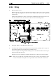
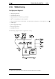
1 Refer to Figure 8.12.1.
Remove the top cover of the radio by unscrewing the four cover screws, remove
the D-range blanking plate in the rear of the T2000 radio, unscrew the logic PCB
and fold-out.
Position the UIM PCB as shown, and connect the Micromatch connectors P13, P14,
P16, P17 and P18 to S13, S14, S16, S17 and S18 on the T2000 logic PCB.
" 3#6 & *
2 Set up the UIM, as described in Section 8.12.4.
3 Carefully fold the logic and UIM PCBs back in position, guiding the D-range con-
nector through the hole provided in the T2000 chassis.
Secure using the three logic PCB retaining screws and the three M3x8 screws pro-
vided and refit the top cover.
Plug the D-range assembly provided in the kit into the D-range connector (S21).
Holes are provided in the T2000 chassis for the D-range plug locking screws.
Use the two black 4-40 Taptite screws provided in the kit to form the threads.