
User's Manual Part 6


!4&)
;*#8
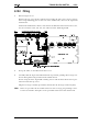
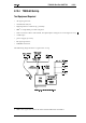
Provision has been made on the T2000-60 PCB for different application requirements.
The PCB links are either solder shorted or fitted with 0Ω SMD resistors.
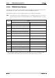
The following table sets out the linking options on the T2000-60 UART PCB.
This table refers only to T2000-60 issue 01 (i.e. PCB IPN 220-01251-01), or later.
For a description of how to identify PCBs, refer to “PCB Identification”, on page
7.2
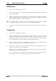
* The analogue signals provided by the UIM must be set up according to the
requirements of the AE (bearing in mind the UIM maximum output levels).
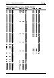
Link
Option
CE controlling radio with AE fitted
*
CE controlling radio with no AE fitted
LINK1
LINK3A
non-processed audio
(DET-AF-OUT connected to RX-AUDIO)
LINK3B
processed audio (de-emphasised)
(RX-GTD-AF connected to RX-AUDIO2)
LINK4A
processed audio (pre-emphasised)
(TX-AUDIO connected to TX-LINE-IN)
LINK4B
non-processed audio
(TX-AUDIO connected to TX-SIG-IN)
LINK5A
T2020
(SQULCH/HUSH to RX-GATE)
LINK5B
T2040
(SQULCH/HUSHconnected to HUSH)
LINK6 no handshaking required
LINK7 no handshaking required
LINK8
normal operation
(removal of this link disables the audio mute)
LINK9
normal operation
(this link provides a line termination resistor)
LINK10
normal operation
(removal of this link disables the audio mute)