
User's Manual Part 6


!4&)
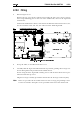
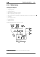
The following diagram shows the pin designations of S21, viewed from the rear of the
radio.
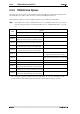
56 -$.
11 CTSA
Clear to send in A
Handshaking input for port A. This signal complies with the
electrical requirements of the RS-232 specification.
12 SQULCH/HUSH
Auxiliary output: receiver audio valid
Signal indicates valid audio is being output from RX-AUDIO.
This output is link selectable between the following signals:
1. RX-GATE
(P14 pin 4)
Receiver Gate:
received audio mute control
line.
Logic high = muted.
5V CMOS logic.
2. HUSH
(P14 pin 12)
External Device Mute:
controls muting of
an external device during radio activity.
Logic high = muted.
5V CMOS logic output.
13 /PTT-FRM-OPT
Transmit request in
Press To Talk: active low transmit request input.
5V CMOS logic input.
14 DTRA
Data terminal ready out A
Handshaking output for port A. This signal complies with the
electrical requirements of the RS-232 specification.
15 TX-AUDIO
Transmit audio in
Audio input to the radio. This input is link selectible between
one of the following signals:
1. TX-SIG-IN
(P13 pin 8)
Transmit signal:
transmit audio input, post
processing.
Input impedance = 600
Ω
or high imped-
ance. Requires 250mVrms at 1kHz to pro-
duce 0 to 80% of full system deviation
(adjustable).
2. TX-LINE-IN
(P13 pin 6)
Transmit audio:
transmit audio input,
before pre-emphasis.
Input impedance = 600
Ω
or high imped-
ance. Requires 110mVrms at 1kHz to pro-
duce 0 to 80% of full system deviation
(adjustable).
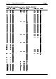
S21
Pin No.
Signal Description
51
10
6
1115
PCB