
User's Manual Part 2


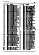

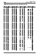
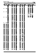

To assist in locating components and labelled pads on the PCB layouts and circuit dia-
grams, a component grid reference index has been provided. This index lists the compo-
nents and pads in alphabetical order, along with the appropriate alphanumeric grid
references, as shown below.
!
Reading a circuit diagram is similar to reading a road map, in that both have an alpha-
numeric border. The circuit diagrams in this manual use letters to represent the horizon-
tal axis, and numbers for the vertical axis. These circuit diagram ‘grid references’ are
useful in following a circuit that is spread over two or more sheets.
When a line representing part of the circuitry is discontinued, a reference will be given
at the end of the line to indicate where the rest of the circuitry is located. The first digit
refers to the sheet number (printed on the bottom right hand corner of the circuit dia-
gram) and the last two characters refer to the location on that sheet of the continuation
of the circuit (e.g. 1-D4).
If more than one line is represented (indicated by a double thickness line), a dot with a
reference label will follow the route each individual line represents.
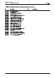
circuit diagram
reference
P
C
B layout
reference
components listed
in numerical order
layer number:
1 = top side layer
2 = bottom la
y
er
(
2 la
y
er PCB
)
component location
on the layer
sheet name or number
e.g. PA = Power Amplifier
component location
on the sheet