
User's Manual

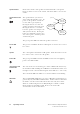


Table Of Contents

TB8100 Installation and Operation Manual Operating Controls 27
© Tait Electronics Ltd June 2003
Microphone
Channel Button and
LEDs
The microphone channel button
selects which base station (BS) the
microphone is connected to. At
power-on both base stations are
selected. Pressing the button once
will connect the microphone audio to
base station 1. Pressing the button a
second time will connect the audio to
base station 2. Pressing the button for
a third time returns to the start of the
sequence, with the microphone audio
connected to both base stations.
The green LED is lit when the microphone audio is connected to its
associated base station.
3.2 Reciter
The only controls on the reciter are the rotary hex switch mounted on the
front panel, and the indicator LEDs visible through a slot in the front panel.
Hex Switch This switch is used to assign an identity number to each base station in the
BSS. For example, the reciters in a dual base station system would be
numbered “1” and “2”. The reciter with the lowest hex number becomes
the “control” reciter. In a single base station system, the hex switch on the
reciter is set to “1”.
power on
BS1 selected
BS1 LED on
BS2 selected
BS2 LED on
BS1 and BS2 selected
BS1 and BS2 LEDs on
press
press
press
Figure 3.2 Operating Controls on the Reciter
b
indicator LEDs
c
hex switch
c
b