
User's Manual

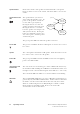


Table Of Contents

TB8100 Installation and Operation Manual Operating Controls 29
© Tait Electronics Ltd June 2003
AC Module On/Off
Switch
This switch turns the AC input to the PMU on and off. Note that this
switch breaks only the phase circuit, not the neutral.
DC Module On/Off
Switch
This switch turns the DC output from the PMU on and off. It is recessed
to prevent the DC module being accidentally switched off, thus disabling
the battery back-up supply.
Note that this switch disables only the control circuitry - the DC input is
still connected to the power circuitry.
Warning!! These switches do not totally isolate the internal
circuitry of the PMU from the AC or DC power
supplies. You must disconnect the AC and DC
supplies from the PMU before dismantling or
carrying out any maintenance. Refer to the
service manual for the correct servicing proce-
dures.
Indicator LEDs These LEDs provide the following information about the state of the PMU:
■ steady green - the PMU is powered up
■ flashing green - the PMU has no application firmware loaded; you can
use the Service Kit software to download the firmware
■ flashing red - one or more alarms have been generated; you can use the
Service Kit software to find out more details about the alarms.
Figure 3.4 Operating Controls on the PMU
b
AC module on/off switch
d
indicator LEDs
c
DC module on/off switch
bc
rear view
d
front view