
User's Manual


ii Appendix 1: 12V PA TB8100 Installation and Operation Manual
© Tait Electronics Limited December 2004
Overview of Inputs and Outputs
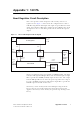
This section identifies the main input and output connections for the
TB8100 BSS with 12V PA. Figure 1.2 below identifies the connections at
the front of the base station, and Figure 1.3 on page iii identifies those at the
rear. Refer to the “Connection” chapter for more details.
Important The system control bus terminating circuitry board must be
connected to the system control bus at all times. If the
board is disconnected, the state of much of the bus will be
undefined. This may cause corrupted data to be present on
the bus when the reciter reads the states of the switches on
the control panel. This in turn may result in random actu-
ations of microphone PTT, carrier, or speaker key, causing
the BSS to transmit or the speaker to be actuated incor-
rectly.
Figure 1.2 5W or 50W base station inputs and outputs - front view
b
RF input from reciter
f
terminating circuitry for system control bus
c
12VDC low current output for reciter
g
system control bus
d
RF output to PA
h
DC output (for optional reciter fan only)
e
12VDC low current input from PA
bdec
gfgh
PA
reciter