
Install Instructions
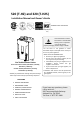
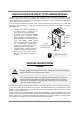

Installation
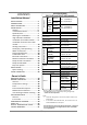
9│Page
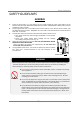
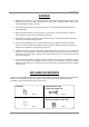
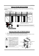
Thedarksquaresindicatethedirectionthe
dipswitchesshouldbesetto.
Leftbankofdipswitches
Leftbankofdipswitches
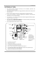
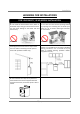
There is a 3” clearance from
the left and right sides of the
unit to combustible and non‐
combustible
surfaces.However, if any
portion or area of the surface
is exposed to the exhaust
fumes(i.e.directlytothesides
of the vent cap), that surface
mustbeatleast24”
away.
Keeptheclearances.
2,500to4,000ft
4,000 to5,000 ft
Altitude
HIGH‐ALTITUDEINSTALLATIONS
Checktheelevationwhereyourwaterheaterisinstalled.Setdipswitchesshowninthetablebelow
dependingonthealtitude.Thesedipswitches(No.5andNo.6)areonthecomputerboardontheleft
bankonly.
0to2,500ft
(DEFAULT)
Over5,000ft
SwitchNo.5 OFF
ON
OFF
Consult
our Technical
Services
Department
at1‐877‐
737‐2840
SwitchNo.6
OFF OFF ON
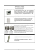
INSTALLATIONFOROUTDOORMODELS
1. InstalltheOutdoormodelonlyinareaswithmild,temperateclimates.
2. TheOutdoormodelshallbewall‐mountedormountedonastand.Locate theOutdoormodelin
anopen,unroofedareaandmaintainthefollowingminimumclearances:
DONOTadjustanydipswitchesontherightbank.
1
2
3
4
5
6
7
8
N
O
9
1
0
N
O
1
2
3
4
5
6
7
8
9
1
0
N
O
1
2
3
4
5
6
7
8
9
1
0
Side3”
Top36”
Side3”
Front24”
Bottom12”
Back0.5”