
User Guide

7 Page
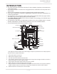
INSTALLATION
GENERAL
1. Follow all local codes, or in the absence of local codes, follow the current edition of the National
Fuel Gas Code: ANSI Z223.1/NFPA 54 in the USA or B149.1 Natural Gas, Propane Installation Code
in Canada.
2. All gas water heaters require careful and correct installation to ensure safe and efficient operation.
This manual must be followed exactly. Read the “Safety Guidelines” Section.
3. The manifold gas pressure is preset at the factory. It is computer controlled and should not need
adjustment.
4. Maintain proper space for servicing. Install the unit so that it can be connected or removed easily.
Refer to the "Clearances" Section on p. 9 for proper clearances.
5. The water heater must be installed in a location where the proper amount of combustible air will
be available to it at all times without obstructions, or the indoor heater may be direct vented.
6. Electrical service to the water heater requires a means of disconnection. This will allow power to
the water heater to be shut off for servicing and safety purposes.
7. Do not install the unit where the exhaust vent is pointing into any opening in a building or where
the noise may disturb your neighbors. Make sure the vent termination meets the required
clearance from any doorway or opening to prevent exhaust from entering a building. (Refer to pp.
11, 26 and 27.) Check local code requirements prior to installation.
8. Carefully plan the installation location of the heater and vent terminations. Contaminants such as
aerosols, lint, and fine powders (including flour) can clog the air intake and reduce the operation
of the fan. This, in turn, can cause improper combustion and reduce the life of the water heater.
Regularly ensure that the area around the water heater, vent termination, and air intake is free of
dust, debris, and other contaminants. In environments with a high level of contaminants (laundry
facilities, hair salons, pet salons, chemical plants, commercial kitchens, etc.), direct venting is
required.
9. The 240 Indoor, 340 Indoor, and 540 Indoor are to be installed indoors only. These units are
equipped with a thermistor and hi-limit switch for the exhaust gas, detecting excess temperatures
within the flue and enabling the unit to safely stop operations if needed. These components are
always monitoring exhaust gas conditions in order to prevent heat damage to ABS, PVC, CPVC,
or polypropylene (Plastic) venting if ABS, PVC, CPVC, or polypropylene is used. If the exhaust
gas temperature exceeds 140 °F (60 °C), these components will enable the unit to safely stop
operations. These components are not installed on the outdoor models since the exhaust vent
is built-in.
If the water heater is used as a direct-vent appliance, the unit requires 3 in (76 mm) or 4 in
(102 mm) combustion air supply pipe. The intake pipe must be sealed airtight. Refer to pp.
13 to 28 for more detail.
Terminating the venting through a sidewall is recommended for the direct-vent system.
Running the exhaust vent and the intake pipe parallel is recommended.
Terminating the exhaust and intake on the same wall/surface is recommended. Terminating in
the same pressure zone allows for pressure balancing, which prevents nuisance shutdowns.
Only install the water heater in a heated area where below freezing temperatures cannot
occur. The warranty does not cover damage caused by freezing.
The water heater must be securely mounted to a wall or other suitable structure.
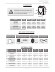
10. The 240 Outdoor, 340 Outdoor, and 540 Outdoor models must only be installed outdoors and only
in an area with mild, temperate climates. The Outdoor model shall be wall-mounted or mounted
on a stand. Locate the Outdoor model in an open, unroofed area and maintain the following
minimum clearances: There is a 3 in. (76 mm) clearance from the left and right sides of the unit
to combustible and non-combustible surfaces.
Installaon
Installaon Manual