Condensing Models On-Demand Water Heater Service Handbook MODELS: ATI-140H-N GTS-140-NIH GT-140-NIH T-H3M-DV-NG ATI-140H-P GTS-140-PIH GT-140-PIH T-H3M-DV-LP ATO-140H-N GTS-140-NEH GT-140-NEH T-H3M-OS-NG ATO-140H-P GTS-140-PEH GT-140-PEH T-H3M-OS-LP THIS SERVICE HANDBOOK IS FOR USE BY QUALIFIED SERVICE PROFESSIONALS ONLY. IF YOU NEED ASSISTANCE, CALL TECHNICAL SUPPORT AT 877-737-2840.
TABLE OF CONTENTS Specifications.................................................................................................................................................................................................................4 Introduction...................................................................................................................................................................................................................5 General Installation Guidelines ............
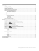
Condensing Models: On-Demand Water Heater Service Handbook • 3 BASICS Service Procedures ......................................................................................................................................................................................................24 Verifying DIP Switch Settings .......................................................................................................................................................................
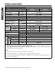
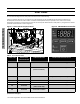
SPECIFICATIONS Table 1: 140 (T-H3M) Direct Vent Indoor and Outdoor* 140 lndoor (T-H3M-DV) 140 Outdoor (T-H3M-OS) Natural Gas Input (Operating Range) BTU/h Min.: 15,000 Max.: 120,000 Propane Input (Operating Range) BTU/h Min.: 15,000 Max.: 120,000 Gas Connection 1/2” NPT Water Connection 3/4” NPT Water Pressure* psi (MPa) 15 - 150 (0.1 - 1.0) Natural gas lnlet Pressure inch W.C. (kPa) Min. 5.0 (1.2) Max. 10.5 (2.6) Propane lnlet Pressure inch W.C. (kPa) Min. 8.0 (2.0) Max. 14.0 (3.
INTRODUCTION This is the safety alert symbol. It is used to alert you to potential physical injury hazards. Obey all safety messages that follow this symbol to avoid possible property damage, serious injury or death. Do not remove any permanent instructions, labels, or the rating plate from either the outside of the water heater or on the inside of the access panels. intended order.
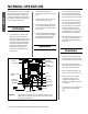
BASICS NORMAL OPERATION Becoming familiar with how a tankless water heater normally operates may help to troubleshoot it. Assuming it is properly installed with appropriate gas, water, and electrical connections, it should operate as follows: 2. The fan activates after the conditions in the previous step are met. 3. Igniter activates. You can hear the buzzing of the spark igniter. 4. The main gas valve, proportional valve, and solenoid gas valves will open. You will hear a deep “clunk clunk” noise.
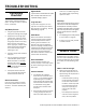
TROUBLESHOOTING To get started, review the following topics. You may also refer to “General Issues,” if necessary. Gas/Water/Electric: • • • • • The gas supply valve should be fully open and the gas line purged. Verify that the correct gas type is being used. Check the supply gas, the gas type dip switch, and the gas type shown on the rating plate. All three must agree in terms of gas type, and your water heater model must be designed for use with that type of gas (natural gas or LP).
resides in the plumbing line, not in the tankless unit. • TROUBLESHOOTING • • • • • • Check for crossed plumbing between cold water lines and hot water lines. See the “Service Procedures” section for instructions. Unit may be hard water scaled. The scale acts as an insulator preventing the heat exchanger from transferring heat to the water. Refer to “Descaling the Unit,” page 29. The unit may not be receiving enough gas. ◦ The gas supply valve may not be fully open.
◦ For LP models, there may not be enough gas left in the propane tank. ◦ Verify that the supply gas pressure is within specification, not only when the heater is in standby, but also while the heater is running on maximum fire. (See “Checking Inlet Gas Pressure/Purging Air from Gas Line” on page 25.) ◦ ◦ • The gas supply pressure may be too low. This may be caused by a malfunctioning gas supply regulator. Check the pressure difference between static and maximum operating pressure.
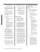
Error Codes All units have self-diagnostics for safety and convenience when troubleshooting. If there is a problem with the unit, a numerical error code will display on the TM-RE42 Remote Controller (if installed) or on the temperature controller of indoor models. Installation-related problems may also produce an error code. If the remote/ temperature controllers are not working, the green LED on the computer board will flash a code pattern.
ERROR CODE GREEN LED ON COMPUTER BOARD SYMPTOM OR ISSUE TROUBLESHOOTING PROCEDURE Abnormal Main/Solenoid Gas Valve, p. 14. 510 Six Flashes 551 Six Flashes 611 Four Flashes Abnormal main OR abnormal solenoid gas valve Abnormal solenoid gas valve Fan motor fault 701 One Flash Computer board fault 711 One Flash 721 Six Flashes 741 N/A 751 N/A 941 Five Flashes Abnormal exhaust temperature (Indoor model only) Abnormal Exhaust Temperature, p. 17.
Incorrect DIP Switch Se ngs gas line is cleared of debris. Error Code: 031 • It is possible that there is a faulty pressure regulator at the gas meter. • For propane units, colder periods of the day result in a cold regulator and may cause this problem. 1. Turn off the power supply. TROUBLESHOOTING 2. Remove front cover and locate the DIP switches at the bottom of the computer board. 3. Refer to “Table 5: DIP Switch Settings”, p. 19. Table 5 lists the correct DIP switch positions.
Unplug both ends of the wiring harness from the igniter assembly and control board, then reconnect them to ensure good connection. Also, verify that the green wire that is part of the circuit is attached to one of the screw connections around the manifold. 6. Verify proper operation of the gas solenoid valves. To do so, turn the power off, then check the resistance of the valves. A normal resistance reading for SV1 and SV2 is 1.35-1.65 kΩ. Normal resistance for SV3 is 2.07-2.53 kΩ.
3.2 TROUBLESHOOTING 3.3 3.4 Remove the computer board to access the inlet thermistor. The computer is fixed in place by a single screw at the top of the board. Remove the screw, pull out the sensor probe. Clean the probe to a silver finish. Do not lose the rubber o-ring that wraps around this sensor. Replace and test. 4. If the error code persists, replace the thermistor. (Thermistor part no. 319143-214.) Air-Fuel Ra o Rod Failure Error Code: 391 1.
within normal range, replace the computer board, part number 320273-369. 6. With the power off, check the resistance of the valve. Normal resistance reading for SV1 and SV2 is 1.35-1.65 kΩ. Normal resistance reading for SV3 is 2.07-2.53 kΩ. If the resistance is out of range, replace the gas valve, NG: part 320273-356, LP: part 320273-354. 4. Verify that the supply gas pressure is within the specified limits. Too high of an inlet gas pressure may cause the main gas valve to jam or could be damaged. 5.
Propor onal Gas Valve / Computer Board Fault 5. Verify that supply gas pressure is within specifications. Error Code: 701 6. Check the resistance across the proportional valve (red, white wires). Normal value is 20-40 Ω. If the resistance is outside this range, replace the gas valve. NG part 320273-356, LP part 320273-354. 1. Verify that the red/white harness is connected at both the proportional valve solenoid and the computer board (PCB). TROUBLESHOOTING 2.
3. Check for any signs of power surges. 4. Check the voltage across the wires coming to the remote. Normal voltage should be 10-25 VDC. If within normal range, replace the remote, part 9009069005. If the voltage is out of range, replace the computer board, part 320273-369. Temperature Controller Problem Error Code: 751 This code is only for the built in controller on the indoor models. (TM-RE41 is printed on the front, lower portion of the controller.
burners will become gas rich and trigger the 101 or 991 code. ◦ TROUBLESHOOTING ◦ To check and clean the burner, refer to “Cleaning the Combustion Components” on page 29. 7.3 To check and clean the fan, see “Cleaning the Combustion Components,” page 29. IMPORTANT: Do not proceed to the next step until this one has been completed and these causes have been ruled out. Lack of combustion air will affect manifold pressure readings. 6. Contact Technical Support regarding the manifold pressure.
DIP SWITCH SETTINGS Figure 9. Use this section to verify DIP switch settings. Each DIP switch has a specific function as shown in the following tables. Generally, they should not require adjustment. Verify the function of each DIP switch carefully before changing any settings. If you have questions, contact the technical service department. NO.
Table 6: Altitude-Specific DIP Switch Settings (Indoor Models) Indoor models: Propane ELEVATION DIPSWITCH SETTINGS OUTPUT FAN MOTOR REDUCTION SPEED CHANGE NO.3 NO.4 NO.
Table 7: Altitude-Specific DIP Switch Settings (Outdoor Models) ELEVATION 2,000 ƚŽ 4,000 Ō͘ 4,000 ƚŽ 6,000 Ō͘ Over 6,000 Ō͘ FAN MOTOR SPEED CHANGE NO.3 NO.4 NO.
WIRING DIAGRAM Figure 10. Wiring Schematic and Check Point Locations W: WHITE R: RED G: GREEN BK: BLACK BL: BLUE O: ORANGE LB: LIGHT BLUE Y: YELLOW BR: BROWN P: PURPLE Indoor Model Only Heater (for the secondary heat exchanger) Heaters Y (for the heat exchanger and water pipes) (for the drain hose) (for the water pipes) TROUBLESHOOTING (for the water inlet) Y (for the water outlet) IG PP Igniter rod PCB Thermostat SV3 B SV2 R O G LB SV1 MV BL BL O.H.C.
TROUBLESHOOTING Notes: Condensing Models: On-Demand Water Heater Service Handbook • 23
SERVICE PROCEDURES Verifying DIP Switch Se ngs Unit Draining and Filter Cleaning Incorrect DIP switch settings can cause a 031 error code. To verify your DIP switch settings, see “Dip Switch Settings” on page 19. 1. Close the manual gas shut off valve. For specific DIP switch settings related to vent length or high-altitude installations, refer to the tables that start on page 19. Additional information is provided in the Installation Manual/Owner’s Guide. 3.
Checking for a Reversed Connec on 1. Turn off cold water supply valve to the water heater. If there are pumps installed in the system for recirculation, ensure that they are turned off. 1. Close cold water supply at the inlet. 2. Turn on all hot water fixtures. 3. If water continues to run through the pressure-relief valve, the system has a reversed connection. • After a brief time, the water should drain completely. • If water continues to run, the fixtures and plumbing system need to be checked.
pressure during maximum combustion, press and hold the “MAX” button on the computer board. (See Figure 8, page 18). • dŚĞ ƟƉ ŽĨ ƚŚĞ ĂƌƌŽǁ ŝŶĚŝĐĂƚĞƐ ƚŚĞ ůŽĐĂƟŽŶ ŽĨ ƚŚĞ ŵĂŶŝĨŽůĚ ƉŽƌƚ͘ ZĞŵŽǀĞ ƐĐƌĞǁ͕ ƚŚĞŶ ĂƩĂĐŚ ƚƵďĞ͘ Figure 14. strong reasons to do so (e.g., high elevation installations). Checking the Manifold Gas Pressure SERVICE PROCEDURES 1. Verify that the gas supply pressure is within the correct operating range when the heater fires at maximum combustion.
5. During this step, DO NOT press the “Increase” or “Decrease” button for more than two seconds at a time. 6. After the gas pressure has been set, deactivate the water heater, remove the manometer tube, and replace the port screw. 7. Verify proper operation. Checking the Overheat Cutoff Fuse (OHCF) 1. Locate the white OHCF which wraps around the heat exchanger. (See Figure 15, page 27.) 2. Find the white clip at the end of the two blue braided wires coming from the OHCF.
Figure 17. two screws on the bottom. 4.1 Clean the flame sensor thoroughly with 100 grit sandpaper or other suitable abrasive. Con nue un l it has a bright finish. 4.2 Clean the air/fuel ratio rod with 100 grit sandpaper or other suitable abrasive. Con nue un l it has a bright finish. 3. Remove the rod assembly as described below. (See Figure 17.) Rod Assembly 3.1 3.
7. Verify proper operation. Descaling the Unit Hard water can cause damage to the copper coils inside of the heat exchangers. Heat exchanger failure due to scale buildup, which results from from hard water, is not covered by warranty. In such cases, a scale inhibitor should be installed before the cold water inlet. Tools and Materials: ● ● ● ● ● Pump: The pump should provide a minimum of 1 gpm through the water heater.
715, p. 70). See also Figure 24, page 35. NOTE: Outdoor models will not include an exhaust thermistor. Its loca on on indoor models is shown on Figure 24, page 35. This will allow you to lay the loose pages beside this manual for easier reference. 2.2 1. Prepare the water heater for service as follows: SERVICE PROCEDURES 1.1 Disconnect power to the water heater by unplugging it from the wall outlet or turning it off at the circuit breaker, as appropriate. 1.
4.7 Remove the screw securing the gas valve to the gas connec on. The screw is located at the bo om, righthand side of the gas valve; see Figure 24, page 35. Li the manifold plate/ gas valve assembly upward to remove it from the gas inlet connec on. (The gas valve and manifold are s ll connected together.) You may need to twist the gas valve/manifold assembly slightly. Manifold Screws: • DO NOT remove the screws shown below (indicated by white, crossed-out circles).
into the slots, star ng at the back and moving forward. Make sure that no contact is made with the gasket; protect it from direct water pressure. Rinse thoroughly. 6.4 Clear excessive water from the burner with compressed air. 6.5 Inspect the gasket. Minor surface tears are acceptable. If the gasket shows major separa ons, replace the gasket before the unit is returned to service. 7.1.3 Slide the fan toward you to remove it from the rear slots that hold it in place. Remove the fan. 7.2 8.
10.Reassemble all items in reverse order. Use this checklist: □ If necessary, refer to the exploded assembly views which start on page 67. □ □ Inspect all gaskets. □ ALL screws must be hand tightened only, especially around the gas valve inlet. □ Reconnect the plastic tube from gas valve to the bottom of the combustion chamber. • All connectors with yellow wire go to the same circuit. They may be reconnected in any order. Figure 23. Solenoid Connector Reinstall the fan.
MAINTENANCE This page is inten onally le blank. The Maintenance sec on begins on the next page.
MAINTENANCE Indoor Model: Over-heat Cutoff Fuse (OHCF) High Limit Switch (Exhaust) Exhaust Thermistor Secondary Heat Exchanger Condensate Drain Tube Pipe Heater Primary Heat Exchanger High Limit Switch (Heat Exchanger) Flame Rod & AFR* Wire Connections Igniter Rod Wire Connection Clip for High Limit Wires Manifold Plate This Screw Secures Computer Board Assembly.
Outdoor Model: Three Screws Secure the Secondary Heat Exchanger to the Case Over-heat Cutoff Fuse (OHCF) Condensate Drain Tube Secondary Heat Exchanger/ Exhaust Vent Pipe Heater Primary Heat Exchanger High Limit Switch (Heat Exchanger) Flame Rod & AFR* Wire Connections Igniter Rod Wire Connection Manifold Plate MAINTENANCE Fuse Box Connector for Overhead Cutoff Fuse (Blue Wires) This Screw Secures Computer Board Assembly.
1. Shut the unit down as follows: Tools: #2 Phillips Screw Driver, 8” long (a magnetic tip is helpful) WARNING! □ □ Disconnect power by opening the circuit breaker or removing the fuses before installing or servicing. Use a non-contact circuit tester to confirm that power is off before working on or near any electrical parts. • 1.1 1.1.1 Shut off Power by disconnec ng the power cord or shu ng off the power disconnect. 1.1.2 Shut off the gas supply to the water heater at the manual gas shutoff valve. 1.
6.1 Disconnect fastener 14-22 (item 458, page 70). 6.2 Remove two heaters and clips (located at top and bo om of tube): ◦ ◦ 9. Remove the Gas Valve and Manifold Plate Assembly: 9.1 Items 413 & 451, p. 70. Items 414 & 451, p. 70. 6.3 Slide the cold connec on tube downward and remove it. Remove the screws that secure the green ground wires to the manifold plate. 9.2 Remove the screws that secure the manifold plate (Figure 24, page 35). 7. Remove the igniter assembly: 7.
9.12 Inspect the o-ring (item 151, p. 69) and gas inlet ring (item 119, p. 69) on the gas connec on for cuts or breaks. If damaged, replace with part number 319143-057 (item 151) and/or 319143049 (item 119). See page 69. 10.Disconnect and remove the fan from the combus on chamber as follows: 10.1 Remove the clear air tube from the bo om of the combus on chamber. If needed, refer to Figure 33, page 41. 10.
13. Follow these steps to remove the heat exchangers: 13.2.1 Remove fastener 14-22 (item 458, p. 70) from the tube on the le -hand side. (This tube connects the primary heat exchanger to the secondary heat exchanger.) 13.1 Slide the heat exchangers down while gradually angling the bo om toward you. 13.2 Separate the primary and secondary heat exchangers as follows: 13.2.2 Remove the four screws that connect the primary and secondary heat exchangers (Figure 34). 13.
NOTICE: Assembly of the secondary heat exchanger is different for the indoor and outdoor models. 1. Remove the following items from the secondary heat exchanger, then INSTALL THEM IN THE SAME LOCATIONS ON THE NEW HEAT EXCHANGER: • Flue gasket (item 154, p. 70) that is located around the exhaust flue. • Exhaust high limit switch (item 466, p. 70): remove the two (2) screws that are holding it in place. • Exhaust thermistor and gasket (items 464 ,465, and 715 on p.
cabinet. You may need to push the assembly up some in order to line up the holes. 6.2 Insert and hand ghten three (3) screws along the top, front por on of the burner (Figure 29, p. 39). 7. Insert the outlet tubing into the water outlet connec on, making sure that the brass ring on the tube goes all the way in and is flush with the top of the outlet connec on (Figure 35). Install fastener 16-25 (stamped on the end of the fastener). See also item 460 on page 70. MAINTENANCE 8.
10.5 A ach the air tube from the bo om of the combus on chamber to the port on the le side of the gas valve. (See page 42, Figure 37.) 10.6 Secure the power cord to the gas valve as shown in Figure 24 on page 35. (See the “Power Cord Moun ng Tab” callout.) Hand-tighten only. • Use the mounting tab and the M4X10 screw. • The mounting hole is located on the left side of the gas valve. 10.7 Line up the manifold plate with the holes on the burner and combus on box.
13.2 Install pipe heaters just below connec on points “A” and “B.” (See page 70.) Secure each one with a clip (item 451). Figure 40. Figure 39. Install Plugs into Receptacles Receptacles (2) (Yellow Wires) 13.3 Install a pipe heater just above connec on point “C.” (See page 70.) Secure it with item 451. MAINTENANCE 15.Hook up the freeze protec on heater wiring: 15.1 At the top of the fuse box loca on, connect two plugs and receptacles as described in Figure 39.
16.2 Insert the connector from the power supply cable to the top port on the fuse box. See Figure 43. 16.3 Use screws to secure three (3) green wires to the bo om, center of the manifold plate. See “Ground Connec ons” in Figure 24, page 35. (There are two moun ng holes for these wires.) The three green wires can be iden fied as follows: • One green wire comes from the power cord. • Two green wires come from connectors on the computer board. Figure 42. Figure 43 Secure fuse box w/ 2 screws.
Replacing the Heat Exchanger (Outdoor Models) Tools: #2 Phillips Screw Driver (a magnetic tip is helpful) WARNING! □ □ □ MAINTENANCE □ Disconnect power by opening the circuit breaker or removing the fuses before installing or servicing. Use a non-contact circuit tester to confirm that power is off before working on or near any electrical parts. • 1.1 Shut Off power and gas supply as follows: 1.1.1 Shut off Power by disconnec ng the power cord or shu ng off the power disconnect. 1.1.
Flame Rod Wire Connector: To remove, pinch flat sides at end with your finger nails, then slide connector off the spade. Figure 44. 6. Remove the igniter assembly: 6.1 Remove the screw that secures the igniter assembly (Figure 25, page 36). 6.2 Disconnect the igniter wire at the igniter rod wire connec on (Figure 25, page 36). Example: Freeze Protection Heaters with Clips 7. Disconnect the blue wires from the high limit switch. See “High Limit Switch (Heat Exchanger),” Figure 25, page 36.
8.8 Remove the brass screw securing the gas valve to the gas connec on. The screw is located at the bo om, righthand side of the gas valve. See Figure 24, page 35. Li the manifold plate/ gas valve assembly upward to remove it from the gas inlet connec on. (The gas valve and manifold are s ll connected together.) (item 151) and/or 319143049 (item 119). See page 69. 9. Remove the burner from the combus on chamber: 9.1 Remove two screws below the burner, at the back. (See Figure 48.) 9.
Figure 51. 10.3 Slide the outlet tube up and out of the outlet water connec on. Remove the tube. 10.4 Remove the three screws at the top of the secondary heat exchanger that are securing it to the case. Refer to Figure 51. 11. Separate the heat exchangers: 11.1 Li the heat exchangers out of the cabinet. 11.2 Separate the primary and secondary heat exchangers. 11.2.1 Remove fastener 14-22 (item 458, p. 70) from the tube on the le -hand side.
3. Disconnect and remove the fan from the combus on chamber as follows: MAINTENANCE 3.1 Remove the 2 Phillips/hex head screws poin ng down from the fan using a #2 Phillips head screw driver. 3.2 Slide the fan toward you to remove it from the slots that hold it in place. 3.3 Complete the steps in “Preparing the New Secondary Heat Exchanger for Installa on (Outdoor Models).” • Flue gasket (item 152, p. 70) which is located around the exhaust. • Flue exhaust port (item 153, p.
Line up the holes, then insert and hand- ghten two (2) hex head screws (item 54). See page 69. 5. Secure the heat exchangers to the case: Insert and hand ghten three (3) moun ng screws as shown in Figure 25, page 36. This will secure the heat exchanger assembly to the heater case. 6. Install the burner into the combus on chamber. (See page 70.) There are grooves on the sides of the combus on chamber; the bo om of the burner will slide along the grooves. 6.
9.6 9.7 MAINTENANCE 9.8 Secure the power cord to the gas valve as shown in Figure 25, page 36. (See the “Power Cord Moun ng Tab” callout.) Hand-tighten only. • Use the mounting tab and the M4X10 screw. • The mounting hole is located on the left side of the gas valve. Line up the manifold plate with the holes on the burner and combus on box. Insert and hand ghten the top center screw on the manifold plate. (See “Manifold Plate,” page 36.) Hand ghten the remaining manifold plate screws.
11.1 Insert the long, straight end of the cold connec on tube into the elbow on the secondary heat exchanger. See connec on point “B” on page 70 (shown in two places). 11.2 Install the flow sensor/ control valve onto the inlet water connec on (Figure 25, page 36). 11.3 Insert the end of the cold connec on tube into the outlet of the flow sensor/control valve. See connec on point “D” on page 70 (shown in two places). 11.4 Install the fasteners: • One 16A fastener. See item 459 on p.
• Item “I” in the schematic (p. 22) uses a separate wiring assembly which includes three wires: yellow, green, and orange.) Install it as shown in the schematic. 15.2 Insert the connector from the power supply cable to the top port on the fuse box. See Figure 64. 16. Complete the wiring connec ons inside the cabinet: • MAINTENANCE • • 19. Open the gas valve slowly and check for leaks. If any gas leaks appear, shut off the gas and disconnect power to the water heater.
5. Remove the computer board (PCB). See Item 701, p. 68; see also Figure 41. 5.1 Disconnect all wires from the PCB. 5.2 Remove the screw at the top and remove the board. 459 on p. 70, which secures the inlet of the flow sensor/ control valve to the inlet water connection. “16A” is marked on the end of this clip. • Tools: #2 Phillips Screw Driver See also Checking the Flow Sensor, page 27. Remove fasteners 16A and 14-22 (items 458, 459) 6.2 Pull the cold connec on tube (item 462, p.
• • 5.2 MAINTENANCE • One green wire comes from the power cord. Two green wires come from connectors on the computer board. If necessary, complete the wiring connec ons inside the cabinet: • • 5.4 Item “I” in the schematic (p. 22) uses a separate wiring assembly which includes three wires: yellow, green, and orange.) Install it as shown in the schematic. Use screws to secure three (3) green wires to the bo om, center of the manifold plate. See “Ground Connec ons” in Figure 25, page 36.
5.3 Disconnect the freeze protec on heater wires. INDOOR MODELS have 6 sets of white connectors with yellow wires (two above the assembly, three below the assembly, and one below the secondary heat exchanger on the right side). OUTDOOR MODELS have 5 sets of white connectors with yellow wires (two above the assembly, and three below the assembly). 8. Remove the Gas Valve and Manifold Plate Assembly: 8.1 Unplug wire connectors from the air/fuel ra o rod (AFR), flame rod, and igniter. See Figure 68. 8.
Figure 69. part number 319143-044 (item 113) and/or 319143045 (item 114). See page 69. Front View of Burner Assembly Three Screws Figure 71. Install Plugs into Receptacles Receptacles (2) (Yellow Wires) 8.12 Inspect the o-ring (item 151, p. 69) and gas inlet ring (item 119, p. 69) on the gas connec on for cuts or breaks. Plugs (2) (Yellow Wires) If damaged, replace with part number 319143-057 (item 151) and/or 319143-049 (item 119). See page 69. Area Beneath Burner (Inside Cavity) Two Screws 9.
1. If a new burner is being installed, then you must complete one of the following steps: Transfer the burner damper (item 112, p. 69) from the original burner to the new burner. Remove two (2) screws (one on each end), then hand tighten them on the new burner. 3. Install the manifold plate/gas valve assembly (item 102, p. 69) to the combus on chamber: 3.1 A ach the white wire connector (blue & red wires) to the solenoid on the back of the manifold plate (Figure 72). 3.
• 7. Install the fuse box assembly to the le side of the manifold plate. (See items 709 & 120, page 69.) Hand ghten two screws to secure it to the manifold plate. 8. Install the computer board (PCB): 8.1 Small feet at the bo om must fit into the corresponding holes in the case. 8.2 Insert and hand ghten the screw at the top of the computer board to secure it to the fuse box. MAINTENANCE 8.3 Connect all of the wires to the computer board.
15. Turn on water to the heater and test for proper opera on. Gas Valve/ Manifold Plate: Removal and Installa on 16. Verify that there are no water or gas leaks. Tools: ● #2 Phillips Screw Driver ● Gas Manometer 17. Outdoor models: Reinstall the front cover. Removal Indoor Models: Insert the temperature controller into the opening of the front cover, then reinstall the front cover. If there are any questions, please contact technical support. 5.1 Disconnect all of the wires from the computer board.
8.4 Unplug the wire connectors at the solenoid valve (SV3); the solenoid valve is a ached to the corner of the manifold plate. See Figure 78. 8.5 Disconnect the air tube off the le side of the gas valve. Installa on DO NOT remove the screws along the interior of the manifold plate. 8.6 Remove the screw on the le side of the gas valve that secures the power cord. 9. Install the gas valve/manifold assembly. (See item 102, p. 69.) Remove the screw securing the gas valve to the gas connec on.
9.4 Install each connector to the solenoid valve with the matching number. • The proportional valve does not have a number and is located at the bottom of the assembly. It has a red and a white wire. Slide the gas valve/manifold plate onto the gas inlet connec on. You may need to rotate the gas valve while sliding it down for an easier fit. The tab on the gas valve connec on should line up behind the tab on the gas inlet connec on. 9.
Secure these wires with the cable clamp on the le side of the cabinet. 12.1 Install the fuse box assembly on the le side of the manifold plate. (See items 703 & 120, page 68.) Hand ghten two screws to secure it to the manifold plate. 13. Install the computer board (PCB): • MAINTENANCE • Small feet at the bottom must fit into the corresponding holes in the case. 13.2 Insert the connector from the power supply cable to the top port on the fuse box. If needed, refer to Figure 75, page 60. 13.
Condensing Models: On-Demand Water Heater Service Handbook • 65 MAINTENANCE This page is inten onally le blank. The Components sec on begins on the following pages.
MAINTENANCE This page is inten onally le blank. The Components sec on begins on the following page.
COMPONENT DIAGRAMS/ITEM NUMBERS Case assembly Indoor model 003 Outdoor model 052 052 007 004 004 052 001 714 001 704 006 702 704 005 052 050 002 002 Temperature controller Temperature remote controller 722 721 724 721 723 056 Condensing Models: On-Demand Water Heater Service Handbook • 67 COMPONENTS Indoor model
COMPONENT DIAGRAMS/ITEM NUMBERS Computer board assembly 701 709 707 710 103 711 716 708 402 408 for Indoor model for Outdoor model 713 706 407 402 060 Fuse box assembly 120 712 710 COMPONENTS 703 053 705 701 712 68 • Condensing Models: On-Demand Water Heater Service Handbook
COMPONENT DIAGRAMS/ITEM NUMBERS Burner assembly Burner assembly 101 104 115 053 053 401 106 107 108 116 708 053 110 Image of fuse box is hidden 109 111 709 117 112 053 103 102 105 Manifold assembly 114 113 053 102 064 707 Gas Valve 150 054 119 120 709 151 057 055 062 053 055 117 118 051 711 Condensing Models: On-Demand Water Heater Service Handbook • 69 COMPONENTS 061
COMPONENT DIAGRAMS/ITEM NUMBERS Waterway Assembly Outdoor Model Indoor Model Secondary Heat Exchanger 417 455 467 063 063 417 463 455 063 Secondary Heat Exchanger 467 458 455 A B 418 467 455 419 465 466 064 455 715 E 455 458 152 455 458 063 A 467 455 463 458 053 463 154 452 153 463 464 413 B 450 053 for Indoor model A 451 413 053 411 058 Heat Exchanger (Primary) 401 E B 451 414 458 402 455 462 COMPONENTS 412 ŽŵďƵƐƟŽŶ Chamber C C 451 413 415 468 461
COMPONENT ITEM NUMBERS Table 10: Component Descriptions and Part Numbers 001 002 003 004 005 006 007 050 051 052 053 054 055 056 057 058 059 060 061 062 063 064 101 102 Part Number Description Case assembly for Indoor model Case assembly for Outdoor model Front cover for Indoor Front cover for Outdoor Intake air port assembly Bracket Junction box Power supply cord assembly Back guard panel Screw M4×12 (W/ Washer) Screw M4×10 (W/ Washer) Screw M4×10 (Coated) Screw M4x10 Hex head screw M4×12 (W/Washer) H
COMPONENT ITEM NUMBERS Table 10: Component Descriptions and Part Numbers Item Number 103 104 105 106 107 108 109 110 111 112 113 114 115 116 COMPONENTS 117 118 119 120 150 151 152 153 154 401 Description Fan motor for Indoor model Fan motor for Outdoor model Burner gasket Fan damper for Indoor model Fan damper for Outdoor model Burner window Rod holder gasket Flame rod Igniter rod Rod holder Rod cap Burner damper Indoor Burner damper Outdoor Manifold gasket A Manifold gasket B Burner holder gasket Pre
COMPONENT ITEM NUMBERS Table 10: Component Descriptions and Part Numbers 402 403 404 405 406 407 408 409 410 411 412 413 414 415 416 417 418 419 450 451 452 453 454 455 456 457 458 459 460 Part Number Description Flow Sensor/ Control Valve Condensate drain port Water inlet Inlet drain plug Inlet water filter Inlet thermistor Outlet thermistor Water outlet Outlet drain plug High Limit switch Overheat-cut-off fuse Pipe heater Inlet heater Drain tube Inlet heater Secondary heat exchanger for Indoor model
COMPONENT ITEM NUMBERS Table 10: Component Descriptions and Part Numbers Item Number Description 461 462 463 464 Flat heater Cold pipe for 140 model Header connection Thermistor fixing plate Exhaust thermistor gasket High limit switch for exhaust Gasket Inlet pipe packing Computer board Rubber grommet Surge box 120 VAC wire for Indoor model 120 VAC wire for Outdoor model 120 VAC Power ON-OFF switch Remote controller wire for Indoor model Remote controller wire for Outdoor model Gas valve wire Flame rod
COMPONENT ITEM NUMBERS Table 10: Component Descriptions and Part Numbers 716 721 722 723 724 Part Number Description Exhaust high limit switch wire Temperature controller for Indoor model Fixing plate Temperature remote controller Remote controller connection wire 140 Model T-H3M Model 319143-501 EK180 320273-684 EK487 N/A EK490 319143-485 TM-RE40 320273-512 EK489 COMPONENTS Item Number Condensing Models: On-Demand Water Heater Service Handbook • 75
Copyright © 2016 A.O. Smith Corporation.