
User Guide

25 Page
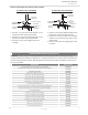
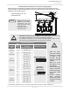
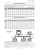
Determine the vent diameter (D) and the total vent length based on the number of water
height (H). See the table below.
Total vent length (L)="H"+"W"
Vent diameter="D"
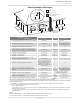
WARNING
A Non-Return Valve must be installed for each water heater. This prevents
the escape of combustion gas through non-operating appliances.
For detailed instructions on the common-venting system, refer to the
instructions that are packaged with the vent parts or web site.
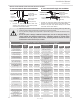
*Diameters of pipes are in accordance with Centrotherm's specifications.
**One elbow is equivalent to 5 ft (1.5 m) linear length, and the maximum number of elbows is 5.
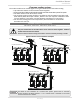
NOTICE
Regarding the clearances
between the exhaust
termination and the
to pp. 26 to 28.
Insert bird screen in
elbow terminals.
Common-venting system
Vent
Diameter*
(D)
Max.
No.of
water
heaters
Max. Vertical and
Horizontal
(Total) Vent Length** (L)
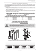
DIP switch settings
4 in.
(110 mm)
2 25 ft (7.6 m)
240 Indoor/340 Indoor
OFF
ON
1 2 3 4 5 6 7 8 9 10
No.6 : ON / No.7: OFF
540 Indoor
(Upper bank of
DIP switches)
OFF
ON
1 2 3 4 5 6 7 8
No.3 : ON / No.4: OFF
5 in.
(125 mm)
2 50 ft (15.2 m)
3 20 ft (6.1 m)
6 in.
(160 mm)
2 100 ft (30.5 m)
3 75 ft (22.9 m)
4 50 ft (15.2 m
5 25 ft (7.6 m)
6 20 ft (6.1 m)
8 in.
(200 mm)
3 100 ft (30.5 m)
4 100 ft (30.5 m)
5 85 ft (25.9 m)
6 65 ft (19.8 m)
7 50 ft (15.2 m)
8 41 ft (12.5 m)
10 in.
(250 mm)
5 100 ft (30.5 m)
6 100 ft (30.5 m)
7 100 ft (30.5 m)
8 100 ft. (30.5 m)
Installaon
Installaon Manual
"H"
Intake
Exhaust
"D"
Elbow terminal
Elbow terminal
"W"
Non-Return Valve
Adjust the appro-
priate DIP switches
according to model
as shown in the
left table. DO NOT
adjust the other DIP
switches.
(Refer to p. 19 for
the location of the
DIP switches.)
Turn off the power
supply to the water
heater before chang-
ing the DIP switch
settings.
Failure to observe
these warnings
could lead to carbon
monoxide poisoning
or death.
WARNING