
User Guide


41 Page
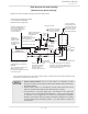
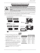
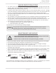
Priority Control Devices such as a flow switch, an Aquastat or other
electronic controller can be used to prioritize the domestic water system over
the heating system.
Follow all local codes, or in the absence of local codes, follow the current
This illustration is a concept design only. The reference to the 1/8
th
hole
in check is only for the State of Massachusetts. There are a wide variety
of variations to the application of controls and equipment presented.
Designers must add all necessary safety and auxiliary equipment to conform
to code requirements and design practice. For more details, contact the
manufacturer.
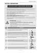
NOTICE
120 VAC
switch or
outlet
Hot water outlet
Unions
Check valve
Electronically controlled
every 6 hours for 60
seconds. Wire to
product approved pump
(used with air-handler)
Cold water supply
3-inch gas exhaust
vent (Discharge must
comply with local and
state codes.) Cannot
be common vented
with other appliances
An approved temperature and pressure
water heater model used
Check valve will have
1/8-inch hole drilling
Atmospheric
vacuum
breaker
valve
Pressure
gauge
Apply correct thermal
expansion tank-size
Check valves
Cold water inlet
Gas inlet
Water
Drain
plug
Hot water
supply and
return to
System installed with reverse
Suggested but not required by
248 CMR
50’-0” maximum distance from
water heater to fan coil.
(Developed length) Not including
NSF-61 product
approved pump
must be installed below
the top of the water heater
as per manufacturer’s
Piping loop
between water
heater and fan
coil shall be in
compliance with
248 CMR
Tempered water to
meet temperature
requirements of 248 CMR
All water piping should be insulated
in accordance with 780 CMR
-Dual-purpose hot water heang-
(Domestic and Space Heating):
Diagrammatic layout of radiant heating and domestic water heater.
The recirculation pump is to provide no less than 2 GPM (7.5 L/min) and no more than 4 GPM (15 L/min)
through each activated unit in the system
Installaon
Installaon Manual
Ball
Valve
Isolation
Valve