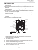
On-Demand Water Heater Installation Manual and Owner’s Guide R D R ANSI Z21.10.3 • CSA 4.3 Models • 540P Indoor • 540P Outdoor If the information in these instructions is not followed exactly, a fire or explosion may result causing property damage, WARNING personal injury or death. - Do not store or use gasoline or other flammable vapors and liquids in the vicinity of this or any other appliance. - WHAT TO DO IF YOU SMELL GAS • Do not try to light any appliance.
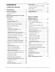
Contents CONTENTS Installation Manual SPECIFICATIONS..............................................4 INTRODUCTION...........................................5 SAFETY GUIDELINES.....................................6 SAFETY DEFINITION.....................................6 GENERAL.......................................................6 INCORPORATED RECIRCULATION PUMP........7 INSTALLATION.................................................7 GENERAL.......................................................
Installation Manual Installation Manual CONGRATULATIONS Congratulations and thank you for choosing our tankless water heater. Before use, we recommend that you read through this installation manual carefully. Keep this manual for future reference. If you need an additional manual, contact the manufacturer or your local distributor. When you call, please tell us the product name and the serial number of your unit written on the rating plate of the water heater.
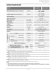
Installation Manual Specifications SPECIFICATIONS Model 540P Indoor 540P Outdoor Natural Gas Input (Operating Range) BTU/h Min: 15,000 Max.: 199,000 Propane Input (Operating Range) BTU/h Min: 13,000 Max.: 199,000 Gas Connection 3/4" NPT Water Connections 3/4" NPT Water Pressure* Natural gas Inlet Pressure Propane Inlet Pressure Weight Dimensions psi (MPa) 15 - 150 (0.1 - 1) " W.C. (kPa) Min 4.0 (1.00) Max. 10.5 (2.61) " W.C. (kPa) Min 8.0 (1.99) Max. 14.0 (3.48) lbs. (kg) inch mm 61.
Installation Manual Introduction INTRODUCTION • This manual provides information necessary for the installation, operation, and maintenance of the water heater. • The model description is listed on the rating plate which is attached to the side panel of the water heater. • Please read all installation instructions completely before installing this product. • If you have any problems or questions regarding this equipment, consult the manufacturer or its local representative.
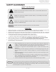
Installation Manual Safety Guidelines SAFETY GUIDELINES SAFETY DEFINITION DANGER WARNING CAUTION NOTICE Indicates an imminently hazardous situation which, if not avoided, will result in death or serious injury. Indicates an imminently hazardous situation which, if not avoided, could result in death or serious injury. Indicates an imminently hazardous situation which, if not avoided, could result in minor or moderate injury. Indicates information considered important but not hazard related.
Installation Manual Installation INCORPORATED RECIRCULATION PUMP This heater incorporates a recirculation pump for homes with an installed circulation system. The pump provides several useful features: • The built-in controller and the remote controller (100276687/TM-RE43) offer two timer settings for pump operation: PUMP TIMER 1 and PUMP TIMER 2. The pump will operate during the times set for TIMER 1 and/or TIMER 2.
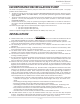
Installation Manual Installation • Installation and service must be performed by a qualified installer (for example, a licensed plumber or gas fitter), otherwise the warranty will be void. • The installer (licensed professional) is responsible for the correct installation of the water heater and for compliance with all national, state/provincial, and local codes. WARNING • The manufacturer does not recommend installing the water heater in a pit or location where gas and water can accumulate.
Installation Manual Installation CLEARANCES Top Maintain all clearances around the water heater. Failure to do so could create a fire hazard, potentially leading to death, serious injury, and/or property WARNING damage. Back Side Side Front Bottom Model Top Bottom Front Back Sides 540P Indoor* 12 in (305 mm) 12 in (305 mm) 4 in** (102 mm) 0.5 in (13 mm) 3 in (76 mm) 540P Outdoor 36 in (914 mm) 12 in (305 mm) 24 in (610 mm) 0.
Installation Manual Installation 1. Temperature remote controller: 100276687 (TM-RE43) 2. Pipe cover: 100112718 (TH-PC03) The temperature remote controller has the following features: • Adjusts set water temperature • Controls the pump operation • Works as a diagnostic tool • provides a concise error code whenever there is a problem with the unit. Refer to pp. 51 to 60 for more information. See the Troubleshooting Section (pp. 64 to 69) for information on possible error codes.
Installation Manual Installation WARNING FOR INSTALLATIONS FOR YOUR SAFETY, READ BEFORE INSTALLATION: Do not install the heater where water, debris or flammable vapors may get into the flue terminal. This may cause damage to the heater and void the warranty. Do not have the vent terminal pointing toward any opening into a building. Do not locate your heater in a pit or location where gas and water can accumulate.
Installation Manual Installation HIGH-ALTITUDE INSTALLATIONS Check the elevation where your water heater is installed. Set DIP switches shown in the table below depending on the altitude. Indoor model No. 2 : OFF No. 3 : OFF No. 4 : OFF No. 2 : OFF No. 3 : ON No. 4 : OFF No. 2 : OFF No. 3 : OFF No. 4 : ON No. 2 : OFF No. 3 : ON No.
Installation Manual Installation VENTING INSTRUCTIONS For 540P Indoor model -General• Improper venting of this appliance can result in excessive levels of carbon monoxide which can result in severe personal injury or death. • Improper installation can cause nausea or asphyxiation, severe injury or death from carbon monoxide and flue gases poisoning. Improper installation will void WARNING product warranty. • When installing the vent system, all applicable national and local codes must be followed.
Installation Manual Installation -Combustion air supply• The guidelines in this section apply to installations within the United States. All U.S. installations must conform to the National Fuel Gas Code, ANSI Z223.1/NFPA 54 (current edition) and local codes. • Canadian requirements differ from the guidelines in this section. In Canada, follow the requirements of B149.1 (Natural Gas and Propane Installation Code, current edition) as well as local and provincial codes.
Installation Manual Installation Your water heater’s BTU/h rating is on the rating plate. The BTU/h ratings should be on the other appliances’ rating plates. If you have trouble determining the BTU/h ratings, contact the manufacturer or have a qualified person determine the ventilation requirements. NOTICE: If you are replacing your old water heater with one that has a higher BTU/h rating, the amount of ventilation required may be greater.
Installation Manual Installation Determine type of ventilation There are several types of ventilation that can be used. The various options are listed below. See also the illustrations on the next page. 1. 2. 3. 4. 5. Direct to outdoors Vertical ducts Horizontal ducts Single opening (not recommended; must be at least 100 in2 (6.5 cm2) . Not appropriate for confined spaces smaller than 50 ft3 (1.42 m3) per 1,000 BTU/h or when getting air from another room.
Installation Manual Installation Combustion air supply options Gable vent to outdoors Install above insulation 12” (305 mm) maximum Outlet air to attic 1 in2 (6.5 cm2) per 4,000 btu/h Confined Space Two permanent Openings Alternate Air Inlet 1 in2 (6.5 cm2) per 4,000 btu/h Inlet air from the crawl space 1 in2 (6.
Installation Manual Installation -Exhaust vent (ABS, PVC, CPVC, or polypropylene vent)The Indoor model can be vented with ABS, PVC, CPVC, or polypropylene (temperature rated up to 149 °F). Vent material certified to ULC S636 standards is recommended in the USA. In Canada, plastic venting must be certified to ULC S636 standards.
Installation Manual Installation -DIP switch settings for vent length- Typical installations using PVC, CPVC, ABS, or polypropylene vent Horizontal Installation Vertical Installation Wall Hanger Roof Roof flashing Hanger Fire stop Connect between exhaust vent collar and piping. See the instructions on p.20. For details of the optional items, refer to the Installation manual for each optional item.
Installation Manual Installation 3" (76 mm) vent connection 1. Connect 3" (76 mm) couplings directly on the exhaust and intake vent collar of the water heater. 2. Connect 3" (76 mm) straight pipes to the couplings.
Installation Manual Installation Set DIP switches shown in the table below depending on the vent diameter and length. Lower bank of DIP switches DIP switch settings : Single vent pipe installations No. 3 : O N No. 4 : OFF • • WARNING • No. 3 : OFF No. 4 : OFF 12 34 56 78 ON 12 34 56 78 ON 12 34 56 78 Lower bank of DIP switches ON DIP switches 12 34 56 78 Vent length 3" (76 mm) 4" (102 mm) venting venting 5 to 45 ft 5 to 50 ft (1.5 to 13.7 m) 46 to 70 ft (1.5 to 15.2m) 51 to 100 ft (13.
Installation Manual Installation CENTROTHERM PP VENTING (Polypropylene) WARNING! Do not mix parts or fittings of different material types, and do not mix pipe, fittings, or joining methods from different manufacturers. Combustion exhaust can contain carbon monoxide and must be properly vented outside. Breathing abnormal amounts of carbon monoxide can result in serious injury or death.
Installation Manual Installation -Exhaust vent (Stainless steel vent)This is a Category IV appliance and must be vented accordingly. The vent system must be sealed airtight. All seams and joints without gaskets must be sealed with high heat resistant silicone sealant or UL listed aluminum adhesive tape having a minimum temperature rating of 160 °F (71 °C). For best results, a vent system should be as short and straight as possible.
Installation Manual Installation Set DIP switches shown in the table below depending on the vent diameter and length. DIP switch settings : Single pipe and Direct vent installations No. 3 : O N No. 4 : OFF • • WARNING • 12 34 56 78 ON Lower bank of DIP switches 12 34 56 78 Vent length DIP switches 4" (102 mm) venting 5 to 50 ft 51 to 100 ft (1.5 to 15.2m) (15.3 to 30.5 m) (DEFAULT) ON Vent diameter Lower bank of DIP switches No. 3 : OFF No.
Installation Manual Installation Approved Category IV, Single Wall, Venting Suppliers and Part Numbers WARNING! Do not mix parts or fittings of different material types, and do not mix pipe, fittings, or joining methods from different manufacturers. Combustion exhaust can contain carbon monoxide and must be properly vented outside. Breathing abnormal amounts of carbon monoxide can result in serious injury or death.
Installation Manual Installation -Common-venting system- The Indoor model can be vented together using the same exhaust and intake venting. • Up to 8 water heaters can be common-vented together. • A non-return valve (100113130) must be used for each water heater that is part of the system. • The water heaters must all be direct-vented. • The common-venting system shall be in accordance with the National Fuel Gas Code, ANSI Z223.1/NFPA 54 and/or B149.
Installation Manual Installation To determine the dimension of a common-venting system Determine the vent diameter (D) and the total vent length based on the number of water heaters installed. The total vent length (L) consists of the horizontal width (W) and the vertical height (H). See the table below.
Installation Manual Installation -Vent termination clearancesInside corner detail V = Vent terminal X = Air supply inlet G = Area where the terminal is not permitted V D H A V L E V B B C Fixed closed Operable V F B Fixed Operable closed V B V M J A X V X V B V K Regulator vent outlet B Canada Direct-vent and other than DirectDirect-vent vent U.S.
Installation Manual Installation -Clearances for sidewall terminationsPlease follow all local and national codes in regards to proper termination clearances. In the absence of such codes, the clearances below can be used as guidelines. Local codes supersede these guidelines. WARNING Exhaust Termination Multiple Sidewall Terminations An exhaust termination must be at least 1 ft (305mm) away from another exhaust termination.
Installation Manual Installation Exhaust and/or direct vent sidewall terminations should be at least 2 ft (610 mm) away from an opposite surface/ wall. Do not place the termination directly in front of an opening into a building. 2 ft (610 mm) min. Exhaust termination -Clearances for rooftop terminations- WARNING Please follow all local and national codes in regards to proper termination clearances. In the absence of such codes, the clearances below can be used as guidelines.
Installation Manual Installation GAS SUPPLY AND GAS PIPE SIZING -General• Check that the type of gas matches the rating plate first. • Ensure that any and all gas regulators used are operating properly and providing gas pressures within the specified range shown below. Excess gas inlet pressure may cause serious accidents. WARNING • Conversion of this unit from natural gas to propane or vice versa will void all warranty. Contact your local distributor to get the correct unit for your gas type.
Installation Manual Installation -Natural gas supply pipingMaximum delivery Capacity of Cubic Feet of Gas per Hour of IPS Pipe carrying Natural Gas with 0.60 Specific Gravity. Based on Pressure Drop of 0.5" W.C. Based on Energy Content of 1,000 BTU/Cubic ft: The water heater requires 199 Cubic ft/hr for the 540P model. Unit: Cubic feet per hour Length Pipe Size 20' 30' 40' 50' 60' 70' 80' 90' 100' 125' 150' 200' Diameter (3 10' .0 m) (6.1 m) (9.1 m) (12.2 m) (15.2 m) (18.3 m) (21.3 m) (24.4 m) (27.
Installation Manual Installation -Measuring inlet gas pressure1. Turn off all electric power to the water heater if service is to be performed. 2. Turn the manual gas valve located on the outside of the unit clockwise to the off position. 3. Failure to follow these steps could lead to fire or explosion, resulting in personal WARNING injury or death. The water heater cannot perform properly without sufficient inlet gas pressure. Below are instructions on how to check the inlet gas pressure.
Installation Manual Installation -Installation with dedicated return lineModel Maximum Pipe length* (Hot Water supply line and Dedicated Return line) 540P Indoor Pipe Diameter 3/4" (19 mm) 1/2" (13 mm) 540P Outdoor 500 ft (152.4 m) 200 ft (61.0 m) *These are equivalent length that includes head loss for elbows, tees, unions, etc. An additional pump may be necessary for circulation systems with longer equivalent pipe lengths.
Installation Manual Installation -Installation without dedicated return lineNOTICE • Cold water supply line must be connected to the "Return inlet". • The "Cold water inlet" must be capped. This piping installation is used when the heater is installed in a system without a dedicated return line. • Install the water supply line to the "Return inlet" water connection. • Install a 3/4" end cap to the "Cold water inlet" connection.
Installation Manual Installation CONDENSATE DRAIN • The water heater does not include a built-in condensate neutralizer cartridge for reducing the pH level of condensate water. If local codes dictate that condensate must be neutralized prior to drainage, a condensate neutralizer must be installed. An accessory Neutralizer assembly (100112159/TH-NT01) is sold separately. (Refer to p. 10.
Installation Manual Installation Installation without neutralizer Installation with neutralizer 3/8" MPT x 3/8" (or 1/2") HB 1/2" Condensate drain tube* 1/2" Condensate drain tube* Overflow bypass* (1/2" Condensate drain tube) 3/8" MPT x 3/8" (or 1/2") HB 1/2" Condensate drain tube* 1/2" MPT x 3/8" FPT (Included with Neutralizer accessory) Neutralizer cartridge (Included with Neutralizer accessory) 1/2" FPT x 1/2" HB (Included with Neutralizer accessory) 1/2" Condensate drain tube* 2" (50 mm) MIN.
Installation Manual Installation ELECTRICAL CONNECTIONS • WARNING • • Follow the electrical code requirements of the local authority having jurisdiction. In the absence of such requirements, follow the current edition of the National Electrical Code ANSI/NFPA 70 in the U.S. or the current edition of CSA C22.1 Canadian Electrical Code Part 1 in Canada. When servicing or replacing parts within the water heater, label all wires prior to disconnection to facilitate an easy and error-free reconnection.
Installation Manual Installation TEMPERATURE REMOTE CONTROLLER -Included accessories - Outdoor model only Be sure that the following items are included with the remote controller which comes with Outdoor model. Temperature remote controller Qty: 1 Screws Manual Remote controller cable* Qty: 2 Qty: 1 Qty: 1 100276687 (TM-RE43) It is also an optional accessory as a second remote for the indoor model. Refer to pp 9 and 10.
Installation Manual Installation 4. Open the Plastic cover and tighten the two Fork terminals beneath the two Remote controller terminal screws on the back of the Main unit (Fig. D-1). Cut out the inlet for the cable from the bottom of the main unit (Fig. D-2). Insert the cable through the inlet. 5. Close the Plastic cover and then hook the Main unit to the Fixing bracket on the Metal plate. (Fig. B) 6. Attach the Frame back onto the remote. Fig.
Installation Manual Installation EASY-LINK SYSTEM The 540P model water heater can be connected to 540 models as only a PARENT unit in an EasyLink System. • The Easy-Link System allows up to 4 units to manifold together with communication cables. • In the Easy-Link System, one unit must be designated as a PARENT unit by changing one of its DIP switch settings. The other units are CHILD units. The 540P model must be a PARENT unit and cannot be a CHILD unit.
Installation Manual Installation (A) 540P model computer board • WARNING • • • To change the DIP switch settings for the Easy-Link System, locate the middle bank of DIP switches at the upper left of the computer board of 540P. DO NOT adjust any other DIP switches . Turn off the power supply to the water heater before changing the DIP switch settings. Failure to observe this warning could result in carbon monoxide poisoning or death. Easy-Link connector is identified by a label.
Installation Manual Applications APPLICATIONS -Combination potable water heating and space heating- WARNING • This water heater is suitable for combination water (potable) heating and space heating and not suitable for space heating applications only. • In order to purge air in water pipes within a closed-loop system, an air vent and air separator should be installed in the system. Required circulation flow rates are labeled next to each application diagram.
Installation Manual Applications -Dual-purpose hot water heating(Domestic and Space Heating): Diagrammatic layout of radiant heating and domestic water heater per Massachusetts code. All water piping should be insulated in accordance with 780 CMR (Massachusetts energy code) Tempered water to plumbing fixtures.
Installation Manual Initial operation INITIAL OPERATION FOR YOUR SAFETY, READ BEFORE OPERATING • Check the GAS and WATER CONNECTIONS for leaks before firing unit for the first time. • Open the main gas supply valve to the unit using only your hand to avoid any spark. Never use tools. If the knob will not turn by hand, do not try to force it; call a qualified service technician. Forced repair may result in a fire or explosion due to gas leaks.
Installation Manual Initial operation Initial Test Run Start pump operation test by built-in controller or remote controller. Press the ON/OFF button on the controller so the STAND BY LED turns off. Press and hold "INFO." and "PUMP" simultaneously for at least 6. three seconds, then the integrated pump starts operation for five minutes. or or A segment of the zero is lighting as follows in clockwise order during pump operation test. 7. 8. 9. 10.
Installation Manual Initial operation This page is intentionally left blank.
Owner's Guide Operating Safety Owner's Guide CONGRATULATIONS Congratulations and thank you for choosing our tankless water heater. Before use, we recommend that you read through this owner's guide carefully. Keep this manual for future reference. If you need an additional manual, contact the manufacturer or your local distributor. When you call, please tell us the product name and the serial number of your unit written on the rating plate of the water heater.
Owner's Guide Operating Safety OPERATING SAFETY FOR YOUR SAFETY READ BEFORE OPERATING WARNING: If you do not follow these instructions exactly, a fire or explosion may result causing property damage, personal injury or loss of life. A. This appliance does not have a pilot. It is equipped with an ignition device which automatically lights the burner. Do not try to light the burner by hand. B. BEFORE OPERATING smell all around the appliance area for gas.
Owner's Guide Operating Safety DANGER Vapors from flammable liquids will explode and catch fire causing death or severe burns. Do not use or store flammable products such as gasoline, solvents or adhesives in the same room or area near the water heater. Flammable Vapors FLAMMABLES Do not install water heater where flammable products will be stored or used unless the main burner is at least 18” above the floor. This will reduce, but not eliminate the risk of vapors being ignited by the main burner.
Owner's Guide Normal Operation NORMAL OPERATION BUILT-IN CONTROLLER and REMOTE CONTROLLER The illustration below shows an example of the controllers. The exact display may differ from examples. Built-in controller 5 6 Remote controller 7 5 6 8 8 9 1 2 3 9 2 3 4 4 7 1 No. Description Note No. Description Note 1 "ON/OFF" Button Press this button to start or stop operation. 5 "TIME" Button Press this button to set the current time.
Owner's Guide Normal Operation OUTLET WATER TEMPERATURE SETTING -Set temperatureControllers Operation Built-in controller 1. Turn on the 120 VAC power supply to the unit. 2. Press the "ON/OFF" button on the controller in order to turn the controller on. 3. When ON, the STAND BY LED is lit. 4. It shows the set temperature of output water on its display as shown in the picture on the right. (EX.: 120 °F) Remote controller (EX.
Owner's Guide Normal Operation SETTING THE TIME Controllers Operation 1. Built-in controller Remote controller Turn on the 120 VAC power supply to the unit. Press the "TIME" button on the controller in order to set the time. This operation is available regardless of ON/ OFF of the controller. 2. The time in the display will flash. The controllers can only have 24 hours indication of time. 3. Press the "HOT" button or "COLD" button to set the time.
Owner's Guide Normal Operation - Setting pump timers Controllers Operation 1. 2. Built-in controller Turn on the 120 VAC power supply to the unit. Press and hold the "PUMP" button on the controller for at least 3 seconds to enter the pump timer setting mode. This operation is available regardless of ON/OFF of the controller. The ON time for PUMP TIMER 1 will flash, indicating that you can set the start time. 3. Press the "HOT" button or "COLD" button to select the time.
Owner's Guide Normal Operation Controllers Operation 7. Built-in controller Remote controller Press the "HOT" button or "COLD" button to select the time. Press and hold the "HOT" or "COLD" button to adjust the time more quickly. NOTICE: The time is displayed in twenty-four hour clock time. For example, 11:00 is 11:00 a.m. and 23:00 is 11:00 p.m. Press the "PUMP" button when the desired time flashes on the display. 8. The OFF time for PUMP TIMER 2 will flash, indicating that you can set the end time.
Owner's Guide Normal Operation Controllers Operation Built-in controller Remote controller The following steps will set the temperature drop that must occur before the recirculation pump will turn off. 13. Temperature drop below set temp. at which °F pump turns off °C *Preset at the factory. (Default) -5* -10 -15 -20 -25 -30 -35 -3 -6 -8 -11 -14 -17 -19 Press the "HOT" button or the "COLD" button to select the temperature at which the pump will turn off.
Owner's Guide Normal Operation -Display example- The display on the controller indicates which PUMP TIMER is set by displaying a number below the time: 1, 2, or 12. (12 indicates PUMP TIMER 1 and PUMP TIMER 2.) The arrow to the right of ON or OFF indicates the current status of the PUMP TIMER(s). If the current time falls within the time range set for a PUMP TIMER, the arrow will point toward ON. (The timer is ON.
Owner's Guide Normal Operation -Pump operation test- The following procedure will operate the pump. This is useful to verify that the pump is operating properly and to check the water flow rate. Controllers Operation Built-in controller 1. Press the ON/OFF button on the controller so the STAND BY LED turns off. 2. Press and hold "INFO." and "PUMP" simultaneously for at least 3 seconds, then the integrated pump starts operation for 5 minutes.
Owner's Guide Normal Operation Lower bank of DIP switches Set DIP switch shown in the table below. ON No. 5 : OFF DEFAULT • • WARNING • 12 34 56 78 Lower bank of DIP switches ON 12 34 56 78 Manual pump operation No. 5 : ON DO NOT adjust any other DIP switches except the No. 5 of the lower bank of DIP switches for the manual pump operation. Turn off the power supply to the water heater before changing the DIP switch settings.
Owner's Guide Normal Operation ADDITIONAL FEATURES -Information mode- You can get some information about the water heater condition by pressing the "INFO" button. For more information, follow the procedures below: Controllers Operation Built-in controller Remote controller 1. Press the "INFO" button on the controller to enter the information mode. 2. Press the "INFO" button to display the inlet water temperature. Inlet water temperature (EX.: 60 °F) 3.
Owner's Guide Normal Operation SETTING THE TEMPERATURE ON THE PCB (WITHOUT BUILT-IN CONTROLLER or REMOTE CONTROLLER) There are two preset temperatures (120°F (50°C) and 140°F (60°C)) that you can select when the temperature controller is inoperable. To do so, adjust the appropriate DIP switch as shown in the table below. When the remote controller is in normal operation, the set temperature of the remote controller is given priority over the set temperature of the DIP switch settings.
Owner's Guide Normal Operation FREEZE PROTECTION SYSTEM • There are two systems for freeze protection in the water heater-heating block system and recirculation system with the integrated pump. • This water heater comes equipped with heating blocks to protect the unit against damages associated with freezing. When the freeze protection thermostat senses air temperature below 36.5 °F (2.5 °C), the blocks will heat up to prevent freezing of the unit.
Owner's Guide Normal Operation MAINTENANCE AND SERVICE • WARNING • Turn off the electrical power supply and close the manual gas shutoff valve and the manual water control valve before servicing. Failure to do so could result in severe personal injury, or death. • • • • • Clean the cold-water inlet filter. (Refer to the Unit Draining and Filter Cleaning Section on this page.) Be sure that all openings for combustion and ventilation air are not blocked.
Owner's Guide Troubleshooting TROUBLESHOOTING GENERAL PROBLEM TEMPERATURE and AMOUNT OF HOT WATER It takes long time to • get hot water at the fixtures. • • SOLUTIONS Check to see if a recirculation timer is active. If not, it will take time for the hot water to get from the heater to the fixture. Check the recirculation pump for proper flow. The inlet filters on the return and inlet connections may need to be cleaned. The water is not hot • Compare the flow and temperature. See the charts on p. 76.
Owner's Guide Troubleshooting BUILT-IN CONTROLLER AND REMOTE CONTROLLER WATER HEATER PROBLEM Unit does not ignite when water goes through the unit. The fan motor is still spinning after operation has stopped. Unit sounds abnormal while in operation Controller does not display anything when the power button is turned on. • • • • • • • • • Is the flow rate over 0.5 GPM (1.9 L/min)? (p. 51) Is the filter on cold water inlet and return connection clean? (p.
Owner's Guide Troubleshooting ERROR CODES -General- • The units have self-diagnostic functions for safety and convenience when troubleshooting. • If there is a problem with the installation or the unit, the error code will be displayed on the built-in controller or remote controller. • Consult the table on the following pages for the description of each error code.
Owner's Guide Troubleshooting -How error codes display in an Easy-Link SystemError codes will be displayed differently with units installed in an Easy-Link System. It will show both the error code and which unit has the error code. Below is an example of how the error code of "321" is displayed in an Easy-Link System.
Owner's Guide Troubleshooting -Fault analysisIf the error code is displayed on the computer board of the water heater or remote controller and/or temperature controller, please check the following. After checking, consult with the manufacturer. Remote Green Malfunction LED description Diagnosis 031 One Time Incorrect DIP switch setting • Check the DIP switch settings on the PCB (Part #701).
Owner's Guide Troubleshooting Remote Green LED Malfunction description Diagnosis 611 Four Times Fan motor fault • Check for connection/breakage of wires, dust buildup in the fan motor (Part #103) and/or burn marks on the computer board (Part #701). • Check for frozen/corrosion of connectors (Part #103). 631 Four Times Pump fault • Check for connection/breakage of wires in the pump(Part #726). • Check if the water in the pump has frozen (Part #726).
Owner's Guide Components Diagram COMPONENTS DIAGRAM Case assembly Outdoor model Indoor model 052 052 003 007 004 713 052 001 717 717 004 725 002 001 702 002 052 008 052 702 006 005 704 052 050 050 Built-in controller Indoor model Temperature remote controller 723 724 056 722 70 Page
Owner's Guide Components Diagram Computer board assembly 721 715 715 402 701 726 714 402 708 716 715 707 713 722 711 103 709 Surge box assembly 713 706 121 703 71 Page
Owner's Guide Components Diagram Burner assembly Burner assembly 101 104 115 053 053 709 108 107 401 106 053 116 053 110 062 109 111 711 Manifold assembly 709 112 117 053 103 114 102 105 113 065 708 121 054 150 730 119 151 711 055 707 063 714 72 118 051 117 719 062 055 057 Page
Owner's Guide Components Diagram Water way assembly 453 F 413 412 403 458 456 460 472 A 462 418 452 058 418 B 473 064 153 Bypass section 462 468 152 471 468 473 064 467 462 462 E 451 401 718 E B 053 A 470 459 F 454 411 414 415 415 455 451 414 463 D 451 459 454 415 466 C 455 462 463 417 455 052 052 729 456 460 460 458 469 052 410 H Water outlet section 728 D 009 454 408 409 456 465 407 458 416 464 C 450 402 733 461 458 462 404 417 0
Owner's Guide Parts List PARTS LIST Item # 001 002 003 004 005 006 007 008 009 050 051 052 053 054 055 056 057 058 059 060 061 062 063 064 065 101 102 103 104 105 106 107 108 109 110 111 112 113 114 115 116 117 118 119 121 150 151 152 153 Part # Description Case assembly for Indoor model for Outdoor model Front cover for 540P Indoor for 540P Outdoor Intake air port assembly Bracket Junction box Power supply cord assembly Back guard panel Chamber fixing plate Condensate drain port Truss screw M4×12 (W/Was
Owner's Guide Parts List Item # Part # Description 540P (AT-H3P) 450 451 452 453 454 455 456 457 458 459 460 461 462 463 464 465 466 467 468 469 470 471 472 473 701 Primary heat exchanger assembly for 540P model Flow adjustment valve / Flow sensor Bypass valve Water inlet Inlet drain plug Inlet water filter Inlet thermistor Outlet thermistor Water outlet Outlet drain plug Heat exchanger thermistor Hi-Limit switch Overheat-cut-off fuse Pipe heater Inlet heater for Indoor model Inlet heater for Outdoor
Owner's Guide Parts List Item # 713 714 715 716 717 718 719 721 722 723 724 725 726 727 728 729 730 731 732 733 734 735 Part # Description Switch wire with thermostat for Indoor model for Outdoor model Proportional gas valve wire 24V cables for Indoor model for Outdoor model Computer board cover Cable clamp Exhaust thermistor for Indoor model Remote fixing plate Exhaust Hi-limit switch wire Temperature controller for Indoor model Fixing plate Temperature remote controller Pump fixing plate Recirculation p