910 / 910 ASME (T-M50/T-M50 ASME) On-Demand Water Heater Installation Manual and Owner’s Guide For supplying potable hot water ANSI Z21.10.3 and CSA 4.3 ASME model ONLY HLW WARNING If the information in these instructions is not followed exactly, a fire or explosion may result causing property damage, personal injury or death. -Do not store or use gasoline or other flammable vapors and liquids in the vicinity of this or any other appliance.
CONTENTS SPECIFICATIONS………………………. 2 INTRODUCTION………………………… 3 SAFETY GUIDELINES……………….... 5 INSTALLATION………………………….. 6 General………………………………… 7 Included Accessories…….…………… 7 Warning for Installations……………… 8 Outdoor Installation…………………… 9 Indoor Installation…………………...... 10 Direct Intake Vent System……………. 11 Venting Instructions………………...... 12 Gas Supply / Gas Pipe Sizing……….. 16 Water Connections…………………… 19 Pressure Relief Valve………………… 19 Electrical Connections……………......
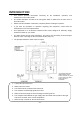
INTRODUCTION This manual provides information necessary for the installation, operation, and maintenance of the water heater. The model description is listed on the rating plate which is attached to the front cover of the water heater. Please read all installation instructions completely before installing this product. If you have any problems or questions regarding this equipment, consult with the manufacturer or its local representative.
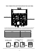
TWO COMBUSTION SECTIONS WITHIN THE 910 (T-M50) Left combustion section Right combustion section The water heater contains two combustion sections. The section that turns on first is whichever section the water heater decides is the primary section. The moment at which the secondary section fires will depend on the total flow rate and set temperature of the water heater: Flow rate at which the secondary section fires ( GPM ) 3.2 2.9 2.6 2.4 2.
SAFETY GUIDELINES WARNING Installation and service must be performed by a qualified installer (for example, a licensed plumber or gas fitter), otherwise the warranty by the manufacturer will be void. The installer (licensed professional) is responsible for the correct installation of the water heater and for compliance with all national, state/provincial, and local codes. PLEASE READ THIS MANUAL CAREFULLY AND FOLLOW ALL DIRECTIONS. GENERAL 1.
INSTALLATION All gas water heaters require careful and correct installation to ensure safe and efficient operation. This manual must be followed exactly. Read the “Safety Guidelines” section at the beginning of this manual. The warranty will not cover damage caused by water quality. Water hardness that leads to scale formation and/or corrosion may affect/damage the water heater. Hard water scaling and/or corrosion must be avoided or controlled by proper water treatment.
GENERAL 1. The manifold gas pressure is preset at the factory. It is computer controlled and should not need adjustment. 2. Maintain proper space for servicing. Install the unit so that it can be connected or removed easily. Refer to p. 9 and p. 10 for proper clearances. 3. The electrical connection requires a means of disconnection, to terminate power to the water heater for servicing and safety purposes. 4.
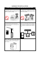
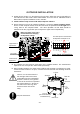
WARNING FOR INSTALLATIONS FOR YOUR SAFETY, READ BEFORE INSTALLATION: Do not install the heater where water, debris or flammable vapors may get into the flue terminal. This may cause damage to the heater and void the warranty. Do not have the vent terminal pointing toward any opening into a building. Do not locate your heater in a pit or location where gas and water can accumulate. Prohibited Prohibited Do not install this water heater under an overhang less than 3 feet from its top or eaves.
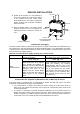
OUTDOOR INSTALLATION 1. Follow all local codes, or in the absence of local codes, follow the most recent edition of the National Fuel Gas Code: ANSI Z223.1/NFPA 54 in the USA or CAN/CSA B149.1 Natural Gas, Propane Installation Code in Canada. 2. Install outdoors only in areas with mild, temperate climates. 3. Ensure that the unit is set for outdoor installation. Locate the central computer board. On the central computer board, locate the lower bank of dipswitches to the right of the 7-Seg.
INDOOR INSTALLATION Top 12” 1. Follow all local codes, or in the absence of local codes, follow the most recent edition of the National Fuel Gas Code: ANSI Z223.1/NFPA 54 in the USA or CAN/CSA B149.1 Natural Gas, Propane Installation Code in Canada. 2. When installed indoors, the water heater shall be located in an area to maintain the following minimum clearances around the unit: Back 0.5” Side 2” Side 2” Front 4” (24” Recommended for Maintenance) Keep the clearances.
DIRECT INTAKE VENT SYSTEM This water heater may be converted to a direct-vent (sealed combustion) appliance by installing an adapter (Part No. 9007669005 (TM-DV50)) which will bring all required combustible air from outside the building. When installing the direct-vent conversion kit, please follow all instructions included with the kit. The water heater must be installed in a location where the proper amount of combustible air will be available to it at all times without obstructions.
VENTING INSTRUCTIONS WARNING: Improper venting of this appliance can result in excessive levels of carbon monoxide which can result in severe personal injury or death. This water heater must be vented in accordance with the section “Venting of Equipment" of the latest edition of the Natural Fuel Gas Code: ANSI Z223.1, All applicable local building codes, Section 7 of CAN/CSA B149.1 Natural Gas in Canada, Propane Installation Code in Canada.
VENT TERMINATION WARNING: Improper installation can cause nausea or asphyxiation, severe injury or death from carbon monoxide and flue gases poisoning. Improper installation will void product warranty. The vent terminator provides a means of installing vent pipe through the building wall and must be located in accordance with ANSI Z223.1/NFPA 54, or in Canada with CAN/CSAB149.1 and local applicable codes.
Horizontal Installation Diagram Wall Vertical Condensation Drain (Install according to local codes) Sidewall Vent Terminator Vent Damper (Recommended for freezing weather conditions: 36°F and below) Rain Cap Vertical Installation Diagram Roof Roof Flashing Vent Damper (Recommended for freezing weather conditions: 36°F and below) Vertical Condensation Drain (Install according to local codes) Regarding the clearance from the terminator to the air inlet or opening, refer to the next page.
VENT CLEARANCES Canada Direct vent and other than Direct Vent U.S.A Direct vent Other than Direct Vent 1 foot A Clearance above grade, veranda, porch, deck, or balcony. 1 foot 1 foot B Clearance to window or door that may be opened. 3 feet 1 foot 4 feet from below or side opening. 1 foot from above opening.
GAS SUPPLY AND GAS PIPE SIZING TO TURN OFF GAS TO APPLIANCE 1. Turn off all electric power to the water heater if service is to be performed. 2. Turn the manual gas valve located on the outside of the unit clockwise to the off position. WARNING: Conversion of this unit from natural gas to propane or vise versa will void all warranty. Contact your local distributor to get the correct unit for your gas type.
Natural Gas Supply Piping Maximum Delivery Capacity of Cubic Feet of Gas per Hour of IPS Pipe Carrying Natural Gas of 0.60 Specific Gravity Based on Pressure Drop of 0.5” WC Based on Energy Content of 1,000 BTU/Cubic Ft.: 910 (T-M50) requires 380 Cubic Ft./hr.
-Measuring inlet gas pressure1. Turn off all electric power to the water heater if service is to be performed. 2. Turn the manual gas valve located on the outside of the unit clockwise to the off position. The water heater cannot perform properly without sufficient inlet gas pressure. Below are instructions on how to check the inlet gas pressure. THIS IS ONLY TO BE DONE BY A LICENSED PROFESSIONAL. 1. Shut off the manual gas valve on the supply gas line. 2.
WATER CONNECTIONS FOR YOUR SAFETY, READ BEFORE OPERATING: ・Do not use this water heater if any part has been submersed under water. Immediately call a licensed professional to inspect the water heater and to replace any damaged parts. ・Do not reverse the hot outlet and cold inlet connections to the water heater. This will not activate the water heater. All pipes, pipe fittings, valves and other components, including soldering materials, must be suitable for potable water systems. 1. 2. 3. 4. 5.
ELECTRICAL CONNECTIONS WARNING: Follow the electrical code requirements of the local authority having jurisdiction. In the absence of such requirements, follow the latest edition of the National Electrical Code ANSI/NFPA 70 in the U.S. or the latest edition of CSA C22.1 Canadian Electrical Code, Part 1, in Canada. CAUTION: When servicing or replacing parts within the water heater, label all wires prior to disconnection to facilitate an easy and error free reconnection.
REMOTE CONTROLLER CONNECTION 1) Disconnect power supply from the water heater. 2) Take off the water heater’s front cover. 3) Please find the remote control terminal using the picture below (located around the lower right-hand side of the water heater). 4) Open the plastic cover of the remote controller accessory, and then attach the fork terminal to the connector base of the backside the remote controller accessory with two screws. Make sure the terminals are firmly fixed.
PUMP CONTROL CONNECTIONS The water heater can be used to control a recirculation pump. Proper pump control helps to preserve the life of the system and saves energy as well. The water heater pump control port is a “normally-open dry contact”, and therefore needs additional components to properly control a recirculation pump. To control the recirculation pump, connect the pump to the “pump terminal” in the water heater as shown in the diagram below.
PUMP CONTROL MODE The water heater provides the four types of the pump control modes. The pump control modes are selected by changing dipswitch settings. The dipswitches are located in the upper bank of dipswitches in the lower-left quadrant of the central computer board in the water heater. (See picture below) A) Recirculation Control: No. 4 ON This mode is for providing hot water as soon as possible like a recirculation usage.
EASY-LINK SYSTEM The water heater can be connected with other heaters of the same model with communication cables to work as a multiple manifold system. The Easy-Link system can connect up to 4 units. A communication cable (gray color) comes with each unit. The cables use 18 gage wire and can be up to 250ft. long all together. You can manifold from 2 units to 4 units without a multi-system controller. A 4-unit system has full automatic modulation between 15,000 BTU/h and 1,520,000 BTU/h.
Easy-Link Connection Procedures 1. Choose one of your units as the “PARENT” unit. 2. “The PARENT” Locate the lower bank of dipswitches to the right of the 7-seg. LED on the central computer board of the unit that you select to be the “PARENT” unit. Change dipswitch No. 8 to “ON”. Do not change any of the dipswitches on the “CHILD” units. 3. Between the “PARENT” and the “CHILD-1” Connect the “PARENT connector” of the “PARENT unit” to the “[1] connector” of the “CHILD-1” unit. 4.
CAUTION If you connect the “[1] (or [2]) connector” of the “PARENT” unit to the “PARENT (or [1]) connector” of the “CHILD-1” unit, the system will not work as the Easy-Link system. The units will operate as individual units.
If a remote controller (optional) is used, it has to be connected to the “PARENT” unit. If the remote controller is connected to a “CHILD” unit, it will only control that particular individual “CHILD” unit and will not control the Easy-Link system as a whole.
An individual cut-off switch is recommended for each unit in a multi-unit system for the purpose of maintenance.
INITIAL OPERATION FOR YOUR SAFETY, READ BEFORE OPERATING: Check the GAS and WATER CONNECTIONS for leaks before firing it for the first time. Open the main gas supply valve to the unit using only your hand to avoid any spark. Never use tools. If the knob will not turn by hand, do not try to force it; call a qualified service technician. Forced repair may result in a fire or explosion due to gas leaks.
NORMAL OPERATION Flow rate to activate the 910 (T-M50) : 0.5 gallon per minute Flow rate to keep the 910 (T-M50) running : 0.4 gallon per minute 1. NORMAL OPERATION WITHOUT REMOTE CONTROLLER 1. Open a hot water tap.* 3. Close the hot water tap. 2. Mix cold water with the hot to get the correct temperature water.
*To change the remote controller’s mode from Default Mode to High Temperature Mode, please follow the procedures below (the remote controller must be installed prior to operating these procedures): DO NOT set to 185ºF if you use your water heater in a recirculation system. This will cause damage to the heater and void the warranty. 1. Turn off power to the remote controller by pressing the “ON/OFF" button. Lamp is OFF to indicate that power is off 2.
FLOW The flow rate through the water heater is limited to a maximum of 14.5 GPM. The temperature setting, along with the supply temperature of the water will determine the flow rate output of the unit. Please refer to the temperature vs. gallons per minute chart on p.51 to determine the likely flow rates based on your local ground water temperature and your desired outlet water temperature combination.
TEMPERATURE SETTINGS There are 8 preset temperatures that you can select from by changing the dipswitch settings on the computer board. The temperature has been preset at the factory to 120ºF (49ºC). If you desire to change the set temperature with dipswitches, please refer to the diagram on below. These temperatures are available: 100ºF, 115ºF, 120ºF, 135ºF, 145ºF, 155ºF, 165ºF, and 185ºF.
MAINTENANCE AND SERVICE WARNING: Turn off the electrical power supply and close the manual gas control valve and the manual water control valve before servicing. Clean the cold-water inlet filter. (Refer to diagram below) Be sure that all openings for combustion and ventilation air are not blocked. The venting system should be checked annually for any leaks, corrosion, blockages or damage. The burner should be checked annually for dust, lint, grease or dirt.
GENERAL TROUBLESHOOTING ~ TEMPERATURE and AMOUNT OF HOT WATER ~ PROBLEM POSSIBLE SOLUTIONS It takes long time to get hot water at the fixtures. The time it takes to deliver hot water from the water heater to your fixtures depends on the length of piping between the two. The longer the distance or the bigger the pipes, the longer it will take to get hot water. If you would like to receive hot water to your fixtures quicker, you may want to consider a hot water recirculation system. (p.
~ WATER HEATER ~ PROBLEM POSSIBLE SOLUTIONS Unit does not ignite when water goes through the unit. The fan motor is still spinning after operation has stopped. This is normal. After operation has stopped, the fan motor keeps running for 35 seconds in order to reignite quickly, as well as push all exhaust gas out of the flue. Is the flow rate over 0.5 GPM? (p. 30) Check for the filter on cold water inlet. (p. 34) Check for reverse connection and cross connection.
TROUBLESHOOTING – ERROR CODES The units are self diagnostic for safety and convenience when trouble shooting. If there is a problem with the installation or the unit, it will display a numerical error code on the remote controller (if installed) or on the 7-Seg LED of the central computer board and section computer board to communicate the source of the problem. Consult the following chart for the cause of each error code.
OPERATING SAFETY FOR YOUR SAFETY READ BEFORE OPERATING WARNING: If you do not follow these instructions exactly, a fire or explosion may result causing property damage, personal injury or loss of life. A. This water heater does not have a pilot. It is equipped with an ignition device that automatically lights the burner. Do not try to light the burner by hand. B. BEFORE OPERATING smell all around the water heater area for evidence of leaking gas.
DANGER Vapors from flammable liquids will explode and catch fire causing death or severe burns. Do not use or store flammable products such as gasoline, solvents or adhesives in the same room or area near the water heater. Keep flammable products: 1. Far away from heater 2. In approved containers 3. Tightly closed 4. Out of children's reach Vapors: 1. Cannot be seen 2. Vapors are heavier than air 3. Go a long way on the floor 4.
APPLICATIONS Space Heating Applications WARNING In order to purge air in water pipes within a closed-loop system, an air vent and air separator should be installed in to the system. Required circulation flow rates are labeled next to each application diagram. These flow rate requirements must be followed. Toxic chemicals used in boiler treatments such as alcohol, glycerol and glycol groups must not be introduced into the system if the system incorporates an open-loop potable water system.
Dual-purpose hot water heating (Domestic and Space Heating): Diagramatic Layout of Radiant Heating and Domestic Water Heater Per Mass.
ADDITIONAL CLEARANCES Please follow all local and national codes in regards to proper termination clearances. In the absence of such codes, the following clearances can be used as guidelines. Local codes supersede these guidelines. For sidewall terminations 2ft. 1ft. 3ft. 2ft. 1ft. 1ft. 3ft. 1ft. 3ft. Inside corner Inside corner Air supply inlet Exhaust termination For multiple sidewall exhaust terminations (e.g. multi-unit systems), an exhaust termination must be at least 1 ft.
OPTIONAL ITEMS 1. Temperature Remote Controller: 9007603005 (TM-RE30) The Temperature Remote Controller has two functions. It allows the output temperature from the water heater to be adjusted within the range of 100 °F to 185 °F, and it also works as a diagnostic tool that will give a concise error code whenever there is a problem with the unit. The temperature options are 100°F, 105°F, 110°F, 115°F, 120°F, 125°F, 130°F, 135°F, 140°F, 145°F, 150°F, 155°F, 160°F, 165°F, 170°F, 175°F, 180°F and 185°F.
COMPONENTS DIAGRAM 3 4 Case assembly 12 3 1 3 2 4 10 2 4 3 11 5 8 718 9 3 6 4 7 13 Computer board assembly 3 The 910 (T-M50) and the 910 ASME (T-M50 ASME) models share the same components.
Burner assembly 110 The 910 (T-M50) and the 910 ASME (T-M50 ASME) models share the same components.
Combustion and Exhaust assembly Other than Part# 444, Part# 445, Part# 446 and Part# 447, the 910 (T-M50) and the 910 ASME (T-M50 ASME) models share the same components.
Water way assembly 910 (T-M50) 411 418 411 419 426 427 411 419 420 428 419 411 422 426 421 427 419 419 419 411 418 419 411 411 411 425 407 427 423 411 424 427 406 406 422 430 910 ASME (T-M50 ASME) 419 439 440 407 425 411 419 411 420 411 441 429 425 421 419 426 442 411 411 418 411 419 443 419 434 431 407 435 427 406 419 430 411 411 407 406 419 436 411 113 437 419 438 449 419 422 425 420 433 3 424 432 427 421 419 419 419 418 411 411 425 4
PARTS LIST Item# Description 001 002 003 004 005 006 007 008 009 010 011 012 013 101 102 103 104 105 106 107 108 109 110 111 112 113 114 Case assembly Brackets Screw M4X10 (w/washer) Screw M4X10 (Coated) Back guard panel Power supply code assembly Junction box Chamber fixing plate Rubber bush Exhaust fixing plate Front cover Air blockage plate Screw M4X12 (w/washer) Burner assembly Igniter Flame rod Igniter rod Damper Rod cap Burner window Rod holder gasket Rod holder Burner holder gasket High voltage ig
Item# Description 136 137 138 139 140 401 402 403 404 405 406 407 408 409 411 412 413 414 415 416 417 418 419 420 421 422 423 424 425 426 427 428 429 430 431 432 433 434 435 436 437 438 439 440 441 442 443 444 445 446 Duct gasket Screw M4X10 Fan damper Screw M3X6 Freeze protection thermostat Heat exchanger assembly for 910 (T-M50) Overheat-cut-off-fuse Hi-limit switch Screw M3X6 Output thermistor Fastener "4-11" O-ring P4 FKM Pipe heater 122 Heater fixing plate O-ring P16 FKM Pan Screw M4X12 (w/washer) F
Item# Description 447 448 449 450 451 701 702 703 704 705 706 707 708 709 710 711 712 713 714 715 716 717 718 719 720 721 722 723 Connecting pipe for 910 ASME (T-M50 ASME) Left cold pipe for 910 ASME (T-M50 ASME) Left hot pipe for 910 ASME (T-M50 ASME) Right hot pipe for 910 ASME (T-M50 ASME) Right cold pipe for 910 ASME (T-M50 ASME) Right and left computer board Central computer board PV-FS wire Thermistor connecting wire Flame rod wire Igniter wire Gas valve wire AC100V wire Right and left computer boa
OUTPUT TEMPERATURE CHART Out Put Temperature vs. GPM (Max. 14.5 GPM) with Various Ground Water Temperature Correct Gas pipe size can be expect this chart 16.0 Out Put Hot Water GPM 14.0 12.0 10.0 8.0 6.0 4.0 2.0 0.0 100 105 110 115 120 125 130 135 140 150 160 165 170 175 180 40 F 10.1 9.3 8.7 8.1 7.6 7.1 6.7 6.4 6.1 5.5 5.1 4.9 4.7 4.5 4.3 185 4.2 50 F 12.1 11.0 10.1 9.3 8.7 8.1 7.6 7.1 6.7 6.1 5.5 5.3 5.1 4.9 4.7 4.5 60 F 14.5 13.5 12.1 11.0 10.1 9.
(1) (2) (3) (4) Heat exchanger An on-demand recirculation system is a system that utilizes either a push-button or other type of manual activation (as opposed to automatic activation with a temperature sensor or timer) to activate the circulation pump. An ondemand recirculation system can use either the existing cold water line as the return line or have its own dedicated return line.