
User's Manual

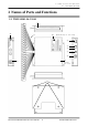
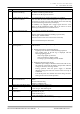
Table Of Contents

Manual No.TDR-MNL-SD01-24-CS141-EN-100
2 Names of Parts and Functions
2.1 TR3X-SD01-24-CS141
3
TAKAYA RFID TR3 Series
No
Name
Feature Description
①
LED to indicate the presence
or absence of RF tag
Displays the status of 24 antennas.
Lit: There is an RF tag on the antenna.
Off: There is no RF tag on the antenna.
②
Terminal block for checking
radio wave condition
It is a terminal block for checking the radio wave condition.
You can check the status of RF transmission / reception radio waves
by inserting an electric wire into this terminal block and connecting
an external measuring instrument (oscilloscope).
In addition, it is equipped with a trigger signal that rises at the
timing of the RF transmission signal, and can be used as an aid in
observing transmitted and received radio waves.
③
Antenna connection cable
It is a cable for connecting the antenna.
Antenna 1CH to 24CH (antenna switching: up to 24 units)
Cable length:580mm±30mm
(from the end face of the case to the antenna connector)
CH can be identified by the mark band.
④
LED for checking the
operating status
It is an LED for checking the operating status. It has the following
A.B. functions.
A. Reading performance confirmation display
Lights up with a dedicated command during inspection.
The reading status of the RF tag is displayed with the
following lighting pattern.
-Only orange lights up: Not read
-Only green lights up: Stable reading
-Lit orange / green: Reading status is unstable
B. Displaying abnormal input voltage
When the input voltage of the main unit becomes 20V or less,
the operation of the main unit shifts to the operation when the
voltage is abnormal, and orange flashes.
During operation when the power supply is abnormal
(blinking orange), the main unit will not be able to accept all
commands.
Turn off the power once and then turn on the voltage of 24V ±
10% again to return to normal operation.
⑤
Communication status display
LED with host device
Displays the communication status (send / receive) with the host
device.
Off: Not communicating
Blinking: Communicating
⑥
Power ON / OFF display LED
Lights green while the power is on.
⑦
Connector for writing
firmware
It is a connector for writing firmware.
Connector type: Mini USB Type-B
⑧
Terminal block for connecting
to host device
A terminal block for connecting to a host device.
Input 24V DC to pin 1.
Connect GND to pin 2.
Connect the RS232C cable to pins 3-5.
⑨
Over current protection
A fuse (socket type) is mounted on the power supply line.