Talk Electronics Thunder 3.1B CD Player User Manual T ALK ELECTRONICS LTD. U NIT 3 IMAGE HOUSE 326 MOLESEY R OAD HERSHAM SURREY KT12 3PD ENGLAND TEL: +44 (0)1276 709966 FAX: +44 (0)1276 682843 E-MAIL: info@talkelectronics.com www.talkelectronics.
Talk Electronics Thunder User Manual INTRODUCTION well-being – do not allow it to come into contact with water. Keep it away from potted plants to avoid those all-too-common watering accidents! To clean the amplifier’s case disconnect it from the wall socket and wipe it with a barely damp, lint-free cloth or chamois leather. If you suspect that water has entered the casework, return the amplifier to your dealer so that he can examine it. Thank you for choosing a Talk Electronics Thunder CD player.
NOTE: These instructions apply in the United Kingdom only – consult your dealer about wiring conventions in other countries. Please ensure that the replacement lead contains a 5A fuse. The power switch mounted on the Thunder’s rear connects and disconnects the mains supply. When mains is connected, the display on the facia will illuminate. If you plan to be away from home for long periods – when, for example, you are on holiday – you can use this switch to power down the CD player completely.
VARIABLE OUTPUT VERSION. TIME: Push once during Play mode to display the time remaining on the current track. Push again to display the time remaining on the disc. Push while the player is in Stop mode to display the total number of tracks and playing time of the disc. Note: if the disc contains more than 69 tracks the display will show “_ _ . _ _” instead of the remaining time. It will show the same if the remaining time exceeds 100 minutes during PROGRAM PLAY mode.
TIMER MODE VOLUME: The volume buttons will operate the volume function on any remote control amplifier that accepts RC5 commands. They are provided solely for your convenience, as there are no volume control functions on the CD player Your player is equipped with a Timer Mode. This allows the player to automatically play a disc when powered on from the mains via the use of an external timer. It is switched off by default at the factory.
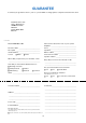
GUARANTEE To extend your guarantee from 1 year to 3 years FREE of charge please complete and return this form T ALK ELECTRONICS LTD. UNIT 3 IMAGE HOUSE 326 MOLESEY ROAD HERSHAM SURREY KT12 3PD ENGLAND FOLD HERE Model: Thunder 3.
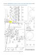
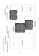
DIAGRAM 1: SP DIF MODE (TO LOCATE THIS AREA PLEASE REFER TO MAIN LAYOUT DIAGRAM) This is an enlarged version of the hatched area on the main layout diagram Place yellow jumper across the pins to turn SP DIF Mode ON 7
DIAGRAM 2: TIMER MODE (TO LOCATE THIS AREA PLEASE REFER TO MAIN LAYOUT DIAGRAM) This is an enlarged version of the hatched area on the main layout diagram Remove yellow jumper from the pins to turn Timer Mode ON 8
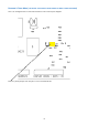
DIAGRAM 3: DC MODE (TO LOCATE THIS AREA PLEASE REFER TO MAIN LAYOUT DIAGRAM) This is an enlarged version of the hatched area on the main layout diagram Move blue jumpers to external position for use with Whirlwind 3.
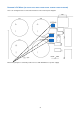
DIAGRAM 4: MAIN LOCATING DIAGRAM 10 1234567890123456789 1234567890123456789 1234567890123456789 1234567890123456789 1234567890123456789 1234567890123456789 1234567890123456789 1234567890123456789 1234567890123456789 1234567890123456789 1234567890123456789 1234567890123456789 1234567890123456789 1234567890123456789 1234567890123456789 1234567890123456789 1234567890123456789 1234567890123456789 1234567890123456789 1234567890123456789 1234567890123456789 1234567890123456789 1234567890123456789 12345678901234
REAR PANEL LAYOUT