INSTALLATION & OPERATION MANUAL IW-HFM-4 Interview Window Intercom System with Paging and Music Options Copyright 2009 Talk-A-Phone Co. All rights reserved. Talk-A-Phone Co. • 7530 North Natchez Avenue • Niles, Illinois 60714-3804 Phone 773.539.1100 • Fax 773.539.1241 • info@talkaphone.com • www.talkaphone.com All prices and specifications are subject to change without notice. Talk-A-Phone, Talk-A-Lert, Scream Alert and WEBS are registered trademarks of Talk-A-Phone Co. Rev.
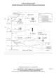
SYSTEM OVERVIEW The Interview Window Intercom System is designed for high-quality one-to-one handsfree voice communications and multi-zone paging. It is built to enhance intelligibility of the human voice through background and outside noises. Installation involves running one 2-pair cable as a paging bus, and 3-pair cable between a master and its substation. Speakers, such as outdoor-rated horn speakers or ceiling speakers, may be grouped in such a way as to create Paging Zones.
INSTALLATION Each IW-HFM-4 Interview Window Hands-Free Master has four buttons. Pressing them will cause the master to communicate with: 1) the sub-station directly in front of them, 2) the paging speakers in their primary zone, 3) the paging speakers of an alternate zone, and 4) all paging speakers in the system.
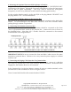
2. Mounting the Optional Gooseneck Microphone or Headset Plug the Gooseneck Microphone into the mini RJ11 plug labeled "GOOSENECK MIC" on the back of the Master. Mount the Gooseneck Microphone so that the Interviewer will be able to speak comfortably. (You may wish to mount the microphone temporarily in order to try different locations before mounting permanently.) For the wireless headset, attach via the mini RJ11 to the plug labeled "HEADSET" and the plug labeled "TEL." on the handset base. 3.
Figure 3. First Master Junction Box Paging Connections 6. Connecting the Paging Cables of Intermediate IW-HF-4 Masters In the Junction Box of intermediate Masters, connect wires from the previous Junction Box and the next Junction Box to the same terminals as shown in Figure 4 below. Note: Connect both shields to the terminal marked “SHLD”. Figure 4. Intermediate Master Junction Box Paging Connections 7.
Figure 5. First Interface Box Wiring 8. Connecting Paging Bus Cable to Intermediate IW-IB-6 Interface Box On the white terminal block included with the Interface Box, connect all wires from the paging bus cable from the previous Interface Box to similar wires from the Interface Box as shown in Figure 6 below. Then connect an identical set of paging bus wires to the same terminals as the first set and continue this cable to the terminal block of the next Interface Box.
Figure 6. Intermediate Interface Box Wiring 9. Connecting Paging Bus Cable to Final IW-IB-6 Interface Box On the white terminal block included with the Interface Box, connect all wires from the paging bus cable from the previous Interface Box to similar wires from the Interface Box as shown in Figure 7 below. For the final Interface Box only leave the 620 Ohm, 1/2Watt Terminating Resistors connected between each pair on the Interface Box side of the terminal block.
Figure 7. Final Interface Box Wiring 10. Connecting Speakers/K-HP-50 to IW-IB-6 Interface Box Before opening the box to perform steps 9 or 10, be sure to unplug the wall transformer from its power source. If there are only one or two speakers in a zone, those speakers may be connected directly to the output terminals on the Interface Box, (terminals A+ and A- located on the Interface board) which has an output of 2 1/2 Watts.
13. Connecting the Master to the Mounting Plate (if master is desk mounted) Using the five Pem fasteners, attach the Master to the Wall (see Figure 1) by simply pressing the Master onto the Pem fasteners. 14. Surface Mounting the Sub-Station Mount the Sub-Station to the wall using the four holes in the mounting plate attached to the back of the unit 15. Adjusting the incoming volume on the Sub-Station. The volume on the Sub-Station is preset at the factory to a level suitable in most applications.
BASIC SYSTEM OPERATION The control panel on the lower front panel of the Master must be set to Position 1 if only the built-in speaker and microphone are being used (no external microphone or headset is being used), Position 2 if the RF Headset is in use, or Position 3 if the Gooseneck Microphone is being used without a headset. Set the Incoming Volume on the control panel to a comfortable level.
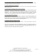
OVERVIEW OF INTERFACE BOX CIRCUIT BOARD Copyright 2009 Talk-A-Phone Co. All rights reserved. Talk-A-Phone Co. • 7530 North Natchez Avenue • Niles, Illinois 60714-3804 Phone 773.539.1100 • Fax 773.539.1241 • info@talkaphone.com • www.talkaphone.com All prices and specifications are subject to change without notice. Talk-A-Phone, Talk-A-Lert, Scream Alert and WEBS are registered trademarks of Talk-A-Phone Co.
TALK-A-PHONE CO. LIMITED WARRANTY Talk-A-Phone Co. warrants Talk-A-Phone equipment against any defects in material and workmanship, under normal use, for a period of twenty-four (24) months from date of installation, provided that Talk-A-Phone receives a completed "Installation Certification" certifying the date on which the system has been installed. An "Installation Certification" card is enclosed with every unit.