Horizontal Pole Mount Installation Manual UNI-PGRM 2020 Edition V4.
PGRM Mount Series Table of Contents Introduction ............................................................................................................................................................... 1 Customer Support ..................................................................................................................................................... 1 Tools Required.....................................................................................................................
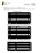
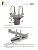
Horizontal Pole Mount Installation Manual Components List The following parts are used in PGRM mount models: Galvanized coated sheet steel components will show rust on cut edges. This is normal and will not affect the structure and function of the mount.
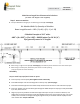
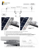
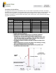
Installation Manual Horizontal Pole Mount Main Beam length Post Placement Calculations (3” and 4” sch-40 pipe is user supplied) Step 1: Measure Modules A. Compute Main Beam Length per the following formula (3” sch-40 pipe) W= Module Width Q= Quantity of Modules Beam Length formula 4.82 + (Q x W) + ((Q – 1) x 1.28) 6 Module Example at 39.5" wide: 4.82” + (6 x 39.5”) + (5 x 1.28”) = 248.22 inches “(or 20'-8 1/4") Pipe generally comes in 21' lengths B.
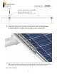
Installation Manual Horizontal Pole Mount Step 3: Install Modules A. Based on the main beam calculations, position and place an end clamp base onto the main beam pipe as shown below at one end. B. Place a level on the clamp to hold a horizontal position at this time. (Final angle adjustment will be done later) C. Tighten the nuts enough to hold the horizontal position as you will be placing modules onto them in next steps. D.
Installation Manual Horizontal Pole Mount E. F. G. H. Lay the first module onto the flat flanges of the end and mid clamp bases. Center the module to overhang equally past the clamps. Loosen the mid clamp, move to fit against the module and re tighten to hold position. Attach under module clamps to the module and end clamp base with the 5/16-18 x 7/8 bolt flange nut and washer as shown, torque to 12ft Lbs. NOTE: The bolt must be up against the module frame. I. J.
Installation Manual Horizontal Pole Mount clamps. K. Loosen the mid clamp, move to fit against the module and re tighten to hold position. L. Install mid clamp top with the 1/4 x 2.5 hex bolts, flat & lock washers and torque to 7ft Lbs. TO AVOID DAMAGE TO THE BOLT AND FASTENER, DO NOT OVERTIGHTEN. M.
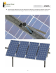
Installation Manual Horizontal Pole Mount A. Loosen all the U-Bolt nuts on the end and mid clamps just enough to allow the entire array to be rotated to the desired angle to the sun, torque all the 3/8 U-Bolt nuts to 20ft Lbs.
Installation Manual Horizontal Pole Mount Installer Responsibility The installer is solely responsible for: i. Complying with all applicable local or national building codes, including any that may supersede this manual; ii. Ensuring that Tamarack Solar and other products are appropriate for the particular installation and the installation environment; iii. Using only Tamarack Solar parts and installer-supplied parts as specified by Tamarack Solar. Substitution parts may void the warranty; iv.
Horizontal Pole Mount Installation Manual Foundation Hole Guidelines The suggestions below are recommendations only. It is the installer’s responsibility to validate foundation parameters prior to installation, as local geotechnical report may be required to assess ground conditions. We recommend consulting with a local engineer familiar with local regulations and build site requirements, including soil conditions, terrain and load criteria (wind, snow, seismic).