Single Arm Pole M Mount IInsstaallattio on Man nuaal 2 2018 Edition v1.03 FFor modells: U UNI‐SA/14 U UNI‐SA/21.
Installation Manual Single A Arm Taable of Contents Inroduction ............................................................................................................... ....................................................... 1 Cu ustomer Supp port .................................................................................................. ....................................................... 1 To ools Required d................................................................................
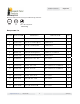
Installation Manual Single A Arm T Tools Required A wrench and screwdriver s that support the e following size e heads: 144 in‐lbs 84 in‐lbs i 5/16” 1/4” 1/4” or #2 Phillips drive d Fo or banding C Componen nts List ITTEM NO. DESCRIPTION PART P NUMBER R USE ED ON\Note es QTY. 1 51-0627-001 Arm, 14" Panel Supp port UNI-SA/14.0 0 1 2 51-3517-010 Arm, 21.5 5" Panel Sup pport UNI-SA/21.5 5 1 3 51-3517-015 Arm, 26" Panel Supp port UNI-SA/26.0 0 1 4 51-3517-020 Bracket, Pole\Flat Mou
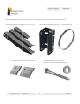
Installation Manual Single A Arm Th he following paarts are used accross our “UN I‐SA” Series Side S of Pole moount and ship w with necessaryy hardware: Paanel Support Arrms (mount spe ecific), 14”, 21.5”or 26” Pole or Flaat Surface Mou unting Bracket Panel Clamps (2x, mount specific 1 or 2 hole) Banding Cllamp (2x) 1//4 to 3/8” Lag Bolts and flat washers (O ptional, for Flaat Wood Surfaace Mounting) info@tamaraccksolar.com | (800) 819‐7236 3 20118 v1.
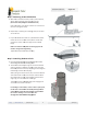
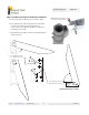
Installattion Manual Single A Arm SStep 1. Mou unting Arm m to PV Module A. With the arm a oriented as shown, inserrt 1/4‐20 x 3/4”” bolt, washer an nd PV module clamp through h each slot. (bent end of clamp facin ng the middle of o the arm) Place a flaat washer, lock washer and hex nut on the end of the bolts and tighten loosely. B. Repeat ste ep 1 attaching the remainingg clamp to the other slot on the e arm. C. Lay the PV V Module face‐down on a prrotected flat su urface.
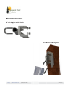
Installattion Manual Single A Arm Sttep 3. Attacching Pane el/Arm Asse embly to Brracket A. Place the panel/arm asssembly on the bracket as sho own. B. Insert 5/1 16‐18 x 3/4” bo olt and flat washer from the in nside out. Place a flat washer, lock washer, and a hex nut on the outside. This orie entation allowss you to tighten the bolt with just j one wrencch. C. Adjust the e tilt of the pan nel as desired, and tighten th he bolts to 144 in‐lbs (dry).
A Alternate mo ounting options 1 1“ sch‐40 pipe p with U‐bolts U urface with h lag bolts Flat su info@ | tam maracksolar.com | (800) 819‐72366 5 20116 v1.
Installattion Manual Single A Arm nstaller Ressponsibility y In TThe installer is so olely responsible e for: i. Complying with all applicable local or na ational building codes, includin ng any that may ssupersede this m manual; ii. Ensuring that Tamarack Solar S and other products are ap ppropriate for thhe particular insttallation and thee installation eenvironment; iii. Using on nly Tamarack Solar parts and installer‐supplied parts p as specifiedd by Tamarack SSolar.