
Installation Guide

Tamarack Technologies 320 Main Street Buzzards Bay, MA 02532 Ph.:508-759-4660, Fx.:508-759-6001
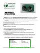
The INFINITY
PRODUCT MANUAL &
INSTALLATION GUIDE
READ AND SAVE THESE INSTRUCTIONS
WARNING: TO REDUCE THE RISK OF FIRE, ELECTRIC SHOCK, OR INJURY TO PERSONS, OBSERVE THE FOLLOWING:
Use this unit in the manner intended by the manufacturer. If you have any questions, contact the manufacturer.
Before servicing or cleaning unit, switch power off at service panel and lock service panel to prevent power from being switched on
accidentally. When the service disconnecting cannot be locked, securely fasten a prominent warning device, such as a tag, to the
service panel.
When cutting or drilling into wall or ceiling, do not damage electrical wiring or other hidden utilities.
Never place a switch where it can be reached from a tub or shower.
Do not use this fan over a tub or shower.
Do not use this fan over cooking appliances.
CAUTION: For General Ventilation Use Only. Do Not Use To Exhaust Hazardous Or Explosive Materials And Vapors
CAUTION: This unit has an unguarded impeller. Do Not Use in Locations Readily Accessible to People or Animals.
The Best Location for The Infinity
1. When selecting fan mounting location, consider the following:
a) Mounting The Infinity as far as possible from the interior air intake or exhaust points will
minimize fan operating noise from being transmitted back through the duct work.
Insulated flexible type duct work will result in much quieter operation.
b) The Infinity location should allow sufficient access for service.
2. Attach fan to the mounting bracket with the nuts and bolts provided. The wiring box should be
positioned for easy access.
3. Using the wood screws provided, attach the mounting brackets to a rafter or support beam at the
selected location.
4. Connect ductwork to the inlet and outlet collars of The Infinity using clamps or duct tape. When
using insulated duct, it is recommended that the inner vinyl core be clamped or taped to the
collars and that the vapor barrier surrounding the insulation be duct taped to the housing.
SPECIFICATIONS:
Duct Size (4): 10”
Duct Collar Length: 3” with Bead
Electrical Requirements: 115V, 60Hz, 3A (Total)
Overall Dimensions: 30”W x 17-1/8”H x 9.5D
Mounting Flange Dimensions 27” x 1-1/2”
Unit Weight 27 Lbs
Air Flow (each motor) 1070 cfm @ .1” Wg