INSTRUCTION MANUAL COMMUNICATIONS RECEIVER iR10 This device complies with Part 15 of the FCC rules. Operation is subject to the following two conditions: (1) This device may not cause harmful interference, and (2) this device must accept any interference received, including interference that may cause undesired operation.
IMPORTANT CAUTIONS READ ALL INSTRUCTIONS CAREFULLY be- RWARNING! NEVER connect the receiver to an AC fore attempting to operate the receiver. outlet. This may pose a fire hazard or result in an electric shock. SAVE THIS INSTRUCTION MANUAL — This instruction manual contains important safety and operating instructions for the IC-R10. EXPLICIT DEFINITIONS The following explicit definitions apply to this manual. WORD DEFINITION Personal injury, fire hazard or electric shock RWARNING may occur.
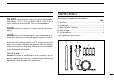
UNPACKING DO NOT use or place the receiver in areas with tempera- Accessories included with the receiver: tures below –10°C (+14°F) or above +50°C (+122°F) or, in areas subject to direct sunlight, such as the dashboard. 1q Antenna............................................................................1 1w Handstrap.........................................................................1 1e Belt clip (with 2 screws)....................................................1 41r Wall charger*...............
TABLE OF CONTENTS IMPORTANT ..................................................................................... i EXPLICIT DEFINITIONS .................................................................. i CAUTIONS ....................................................................................... i UNPACKING .................................................................................... ii TABLE OF CONTENTS .................................................................. iii OPERATING THEORY ...
TABLE OF CONTENTS ■ General ................................................................................................ 51 ■ Memory channel edit ........................................................................... 51 ■ Program scan channel edit .................................................................. 55 ■ EASY mode channel edit ..................................................................... 55 ■ Program scan or EASY mode channel edit .........................................
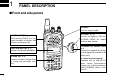
1 PANEL DESCRIPTION ■ Front and side panels SPEAKER Emits the receive audio. FUNCTION SWITCH (pgs. 5, 6) While pushing [FUNC], the secondary functions of switches and controls can be accessed. FUNCTION DISPLAY (p. 3) Indicates the operating condition. KEYPAD (pgs. 5, 6) Numeral and other function keys for tuning and activating functions. 1 CI-V JACK (p. 73) Connect the optional OPC-478 CLONING CABLE for remote control or data cloning. EXTERNAL DC POWER JACK (p.
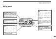
PANEL DESCRIPTION 1 ■ Top panel ANTENNA CONNECTOR (p. 9) Connects the supplied flexible antenna. Be careful when connecting an external antenna (See Operating Notes, p. iv). VOLUME CONTROL [VOL] (p. 10) Adjusts the audio output level. SQUELCH CONTROL [SQL] (p. 11) ➥Varies the squelch threshold point for audio mute. • Pushing [MONI] opens the squelch momentarily. EXTERNAL SPEAKER JACK [SP] Connect an 8 ohm optional speaker or an earphone, if desired.
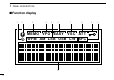
1 PANEL DESCRIPTION ■ Function display 1 2 3 4 5 6 7 8 MEMO VFO EASY VSC AT T WFM AM LSB USB CW AFC A 3 0 9
PANEL DESCRIPTION q SLEEP TIMER INDICATOR Appears while the sleep timer is activated (p. 66). !0 LOCK INDICATOR Appears while the lock function is activated (p. 64). w FUNCTION INDICATOR Appears while the function ([FUNC]) switch is pushed. !1 MULTI-FUNCTION DOT MATRIX Indicates the following items: Opening message (p. 10) Receive frequency (p. 11) Tuning steps (p. 13) Band scope (p. 17) Memory bank and channel number (p. 23) Memory name (p. 31) Memory bank name (p.
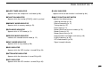
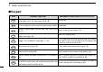
1 PANEL DESCRIPTION ■ Keypad KEY PRIMARY FUNCTION SECONDARY FUNCTION (while pushing [FUNC]) POWER Push for 1 sec. to toggle power ON and OFF. Opening mesNot available sage appears for 1 sec. after power ON (p. 10). MONI Push and hold this switch to force the squelch open (p. 64). Not available TS MODE SET CLR Selects a receive mode: FM, AM, USB, LSB, CW or WFM (p. 12). Clears numeric key input (p. 14). Stops scanning (p. 39). Selects SET mode (p. 59). Toggles VFO or MEMORY mode (pgs. 11, 23).
PANEL DESCRIPTION KEY PRIMARY FUNCTION 1 SECONDARY FUNCTION (while pushing [FUNC]) BSCOPE When FM receive mode is selected in VFO mode: toggles the band scope function (p. 17). 1 VSC Toggles the VSC function ON and OFF (p. 38). 2 SLEEP Selects the sleep timer conditions (p. 66). 3 PROG-S BSCOPE VSC SLEEP 4 1 2 3 AMWS PROG-S AMWS SIGNAVI 5 4 5 6 SIGNAVI MODE-S BANK-S PRIO 6 7 8 9 AFC ATT NB/ANL .
2 Ni-Cd BATTERIES AND ACCESSORIES ■ Charging Ni-Cd batteries ■ About Ni-Cd batteries The supplied Ni-Cd batteries are rechargeable and can be charged approx. 300 times. Charge the batteries before first operating the receiver or when the batteries become exhausted. Ni-Cd battery life If your Ni-Cd batteries seems to have no capacity even after being fully charged, completely discharge them by leaving the power ON overnight. Then, fully charge the Ni-Cd batteries again.
Ni-Cd BATTERIES AND ACCESSORIES 2 ■ Battery installation ■ Charging connections Install 4 AA (R6) size batteries as illustrated below. Confirm that the [CHARGE] switch is ON, then connect the supplied wall charger via an AC outlet as shown below. Remove the cover from the receiver. BC-110A/E/D/V* *Not supplied with some versions. Install 4 AA (R6) size dry cell, alkaline or the supplied Ni-Cd batteries into the receiver.
2 Ni-Cd BATTERIES AND ACCESSORIES ■ Accessory attachment 9 Antenna Belt clip Handstrap Insert the supplied antenna into the antenna connector and rotate the antenna as shown in the diagram below. Keep the jack cover attached when jacks are not in use to avoid bad contacts. Attach the belt clip using the supplied screws. Conveniently attaches to your belt. Attach the handstrap as shown in the diagram below. Facilities carrying.
BASIC OPERATION ■ General Operating the IC-R10 is easy. However, in order to get the most out of its operating potential, please go through the following procedures, step-by-step. Then, try the examples contained at the end of this chapter. 3 ■ Selecting VFO mode 1. Turn power ON 2. Adjust the volume Push [POWER] for 1 sec. to turn power ON. Adjust the audio to a suitable level using [VOL]. • Opening message is displayed for 1 sec.
3 BASIC OPERATION 3. Adjust the squelch 3-1. Adjust the RF gain 4. Select VFO mode Rotate [SQL] maximum counterclockwise, then rotate it clockwise until audio is just muted when receiving no signal for FM, WFM or AM mode. (see right page) Rotate [SQL] maximum counterclockwise, to adjust RF gain to optimum level. When MEMORY mode is selected, push [V/M] to select VFO mode. When SET or TS set mode is selected, push [CLR] to select VFO mode. • The VFO indicator appears.
BASIC OPERATION 3 ■ Selecting a receive mode What are receive modes? Radio signals can be propagated in a variety of ways (or modes). Each mode has its own physical properties that determine to some degree its uses. VFO FM The IC-R10 receives the 6 most common modes: AM, FM, WFM, USB, LSB and CW. When you want to tune a station, you MUST set the receive mode first. The table below shows common uses for each mode. MODE 144.0000 VFO WFM 144.0000 VFO AM 144.0000 VFO LSB 144.
3 BASIC OPERATION ■ Selecting a tuning step What are tuning steps? Tuning steps are the frequency change increments when you rotate the tuning control or operate a scan. The following steps are available: 0.1, 0.5, 1, 5, 6.25, 8, 9, 10, 12.5, 15, 20, 25, 30, 50, 100 kHz and user programmable tuning steps (p. 66). It is important to set the proper tuning step for the type of station you want to listen to. Some tuning steps are determined by frequency band or receive mode and others are set by tradition.
BASIC OPERATION 3 ■ Tuning a frequency (via the keypad) When you know the exact frequency you want to listen to, the quickest way to tune it is by direct keypad entry. Remember that the frequency must be between 0.5 MHz and 1300 MHz. The diagram below shows the correlation between the function display frequency digits and the frequency. VFO FM 1 GHz 100 MHz 10 MHz 1 MHz 300.0000 100 Hz 1 kHz 10 kHz 100 kHz 1. Select the frequency 2.
3 BASIC OPERATION ■ Tuning a frequency (via the dial) When you want to listen to frequencies near the displayed frequency, the easiest way to tune them is with the tuning dial. All signals have what is called an “occupied bandwidth.” They will be received as long as the receiver is tuned anywhere within this bandwidth. Even though the frequency received may not be the central frequency, the tuning step should be made as small as possible (0.
BASIC OPERATION ■ Dial select steps Changing the frequency with the dial select step What are dial select steps? When tuning with the dial, if you want to change the frequency faster than the selected tuning step can, use the dial select function. In VFO mode: Push and hold [FUNC], then rotate [DIAL]. A dial select step is an increment of frequency change much like a tuning step is.
3 BASIC OPERATION ■ Band scope function What is the band scope function? The band scope detects signal availability in the range of ±5 channels (up to ±100 kHz) from the displayed frequency, and displays the result on the multi function dot-matrix display. This gives you a visual reference of current band conditions. In this case, channel refers to sweep step or channel space according to the set tuning step.
BASIC OPERATION 3 Set band scope function q While pushing [FUNC], push [(1)BSCOPE]. VFO FM 144.0000 signal strength lower freq. higher freq. displayed freq. Repeat the above step or push [CLR] to turn OFF the band scope function.
3 BASIC OPERATION ■ Listening example 1 — television broadcast in WFM mode 1. Turn power ON 5. Select the receive mode 6. Select the tuning step Push [POWER] for 1 sec. to turn power ON. Television sound is broadcast in WFM mode. If the receiver is not already in WFM mode: In most countries* television stations are spaced about 50 kHz apart. To select the 50 kHz tuning step: Push [MODE] one or more times until WFM appears in the function display.
BASIC OPERATION (Example 59.75 MHz) 3 (Example 59.25 MHz) 7. Tune the station 7-1. Tune the station 8. Use the tuning dial Use the keypad to enter the frequency — (example 59.75 MHz). Enter the frequency from the 100 kHz digit when you want to change below the 1 MHz digit only — (example from 59.75 MHz to 59.25 MHz). Rotate [DIAL] to search for nearby stations above and below the tuned frequency. [Example] VFO WFM 5 WFM . 9 59 . VFO WFM . 59.2000 [Example] VFO [DIAL] 59. VFO WFM 59.
3 BASIC OPERATION ■ Listening example 2 — airband broadcast in AM mode 1. Turn power ON 5. Select the receive mode 6. Select the tuning step Push [POWER] for 1 sec. to turn power ON. Airband communications are in AM mode. If the receiver is not already in AM mode: Tuning steps for the airband are usually 25 kHz*. To set the 25 kHz tuning step: Push the [MODE] switch one or more times until AM appears in the function display.
BASIC OPERATION 3 (Example 118.00 MHz) (Example 118.925 MHz) 7. Tune the station 7-1. Tune the station 8. Use the tuning dial Enter a frequency of 118.0000 MHz* using the keypad (p. 14). Enter the frequency from the 100 kHz digit when you want to change below the 1 MHz digit only — (example from 118 MHz to 118.925 MHz). Rotate [DIAL] to search for nearby stations above and below the tuned frequency. 1 VFO AM 1 . VFO AM VFO AM 118. 118 118.9000 8 ENT VFO AM 118.
4 MEMORY MODE ■ General What is memory mode? MEMORY mode is the second operating mode—the first being VFO mode. MEMORY mode is used to store oftenused frequencies, their receive modes, attenuator settings (p. 65), as well as skip information for scanning (p. 56). This provides convenient recall and scanning capabilities. Also, frequencies are receivable in MEMORY mode which means you can listen to received signals while you are in MEMORY mode. The IC-R10 has 1000 memory channels for your convenience.
MEMORY MODE 4 ■ Selecting a BANK and memory channel Selecting a BANK channel Selecting a memory channel—1 Selecting a memory channel—2 When your desired memory channel is not stored or you do not want to store a frequency in the displayed BANK, you must change the BANK number. If you want to recall a memory channel which has been memorized, this is the easiest way. If you remember the memory channel number you want to recall, this is the fastest way to recall it. Rotate [DIAL].
4 MEMORY MODE ■ Programming a memory channel — 1 This is the quickest way to memorize a received frequency, along with its receive mode and other information. When you memorize the frequency in this way, the previously memorized data is replaced with the new data. If you do not want to lose the previously memorized data, select a blank channel number before programming (p. 24). 1. BANK and memory channel setting 3. Programming q Select MEMORY mode (p. 23). w Set the BANK and memory channel number (p.
MEMORY MODE 4 ■ Programming a memory channel — 2 This is the simplest method to memorize the received frequency along with its receive mode and other information. 1. Setting receive conditions q Select VFO mode (p. 11). w Set the frequency and receive mode (p. 12). 3. BANK and memory channel setting 4. Programming q While pushing [FUNC], rotate [DIAL] to select the BANK you want to program into. w Rotate [DIAL] to select the memory channel you want to program.
4 MEMORY MODE ■ Programming a memory channel — 3 This is the easiest way to memorize the received frequency, mode and other information along with memory, BANK names, scanning condition, etc. in one operation. 1. Set up q Set the frequency you want to program in VFO mode. w While pushing [FUNC], push [(V/M)MW] to enter memory write mode. 3. Programming details q Push [EDIT] to enter memory programming mode. w Rotate [DIAL] or enter the alphanumeric characters via the keypad to program a memory name.
MEMORY MODE 4 3. Programming details — cont. 3. Programming details — cont. 3 Push [EDIT], then rotate [DIAL] to select receive mode. u Push [EDIT], to display your programmed frequency for confirmation. When the correct frequency is displayed, push [EDIT] for 2 sec. to return to VFO mode. 4 Push [EDIT], then rotate [DIAL] to select the skip scan condition. t Push [EDIT], then rotate [DIAL] to select the attenuator condition. When you want to return to VFO mode immediately, push [EDIT] for 2 sec.
4 MEMORY MODE ■ Programming example 1 — (118.0250 MHz; AM to channel B07) 1. BANK and memory channel setting 2. Data setting 3. Programming the data q Push [V/M] to select MEMORY mode. w While pushing [FUNC], rotate [DIAL] to select BANK “B”. q Push [V/M] to select VFO mode. w Push [MODE] one or more times to select AM mode. While pushing [FUNC], push [(V/M)MW] for 2 sec. FUNC + MODE B: [DIAL] e Push [0] and [7] to enter the memory channel number.
MEMORY MODE 4 ■ Programming example 2 — (59.75 MHz; WFM to channel A45) 1. Setting the frequency 2. Set the BANK and memory channel 3. Programming the data q Push [V/M] to select VFO mode. w Push [MODE] one or more times to select WFM mode. 1 While pushing [FUNC], push [(V/M)MW] to enter memory write mode. 2 While pushing [FUNC], rotate [DIAL] to select BANK “A”. While pushing [FUNC], [(V/M)MW] for 2 sec. MODE VFO WFM 144.
4 MEMORY MODE ■ Programming example 3 — (121.5 MHz, EMER.,AM, SKIP: OFF, ATT: OFF, Aviation to channel F01) 1. Setting the frequency 2. BANK and memory channel setting 3. Programming details q Push [V/M] to select VFO mode. w Rotate [DIAL] or push numeral keys to enter 121.5 MHz. q While pushing [FUNC], push [(V/M)MW]. w While pushing [FUNC], rotate [DIAL] to select BANK “F”. q Push [EDIT] to enter memory setting mode. 1 VFO FM 2 1 121.
MEMORY MODE 4 3. Programming details — cont. 3. Programming details — cont. 3. Programming details — cont. t Push [EDIT] to change the receive mode item. y Rotate [DIAL] to select AM mode, then push [EDIT] to change the item. i Rotate [DIAL] to select the OFF position for attenuator setting, then push [EDIT]. !1 The display shows the programmed frequency for confirmation; push and hold [EDIT] for 2 sec. if the frequency is correct.
4 MEMORY MODE ■ Memory copy What is the memory copy function? The memory copy function copies the contents (minus BANK names) of the selected memory channel to VFO or to another memory channel. This is quite useful when you want to search for signals around the displayed frequency or when you want to edit memory channels. Copy to VFO mode Copy to the other memory channel q Push [V/M] to select memory mode. (p. 23) w Select the BANK and memory channel you want to copy (p. 24).
MEMORY MODE ■ Copying example 1 (59.7500 MHz, WFM, A45 to VFO) 1 Push [V/M] to select memory mode (p. 23). 2 Select the memory channel A45 (p. 24). 3 While pushing [FUNC], push [(V/M)MW] for 2 sec. to copy the contents of memory A45 to VFO. 4 ■ Copying example 2 (118.0250 MHz, AM, B07 to F02) 1 Push [V/M] to select memory mode (p. 23). 2 Select the memory channel B07. (p. 24) 3 While pushing [FUNC], MEMO AM push [(V/M)MW]. B07 118.0250 • VFO mode is automatically selected.
5 SCANNING OPERATION ■ General FULL SCAN Scan types The IC-R10 has 2 major scan types: PROGRAMMED SCAN and MEMORY SCAN. These, in turn, can be subdivided into 3 variations of each, making a total of 6 scan operations. Additional scanning functions are available to “fine tune” scanning operation. 0.5 MHz 1300 MHz The following diagrams illustrate the operation of each scan type. Step-by-step instructions on how and when to use each scan type follow these diagrams.
SCANNING OPERATION PROGRAM SCAN 5 AUTO-MEMORY WRITE SCAN BANK "Q" Programmed edges 00 01 02 03 04 Programmed scan edges • • • 1234.5670 1235.6780 1235.8900 1240.0500 --------------- 98 99 --------------- Repeatedly scans between two user-programmed frequencies (scan edges). Same as PROGRAMMED SCAN except that paused frequencies are automatically stored in memory channels Q00–Q99.
5 SCANNING OPERATION ■ Before scanning Set the following conditions before scanning. 1. Set receive mode 2. Set the volume and squelch levels Set any receive mode EXCEPT USB, LSB and CW. Set [VOL] to a suitable audio output level. Set [SQL] so that the noise audio is just muted. INFORMATION What happens when you rotate the tuning dial during scanning? While scanning— Scanning direction is changed.
SCANNING OPERATION Set the VSC Set the scan delay Set the VSC ON if necessary. While pushing [FUNC], push [(2)VSC] (VSC indicator appears). Set the scan delay. While pushing [FUNC], push [(CLR)SET], then push [EDIT] one or more times until SCAN DELAY appears (p. 62). Appears VFO FUNC FM + SIGNAVI 5 Rotate [DIAL] to set the scan delay time. VSC 144.0000 6 While pushing [FUNC], push [(2)VSC) to turn OFF the VSC (VSC indicator disappears).
5 SCANNING OPERATION ■ Full scan ■ Memory scan This is the simplest scanning operation, searching the full frequency range (0.5–1300 MHz) in the selected receive mode and tuning step. This is the simplest way to search for all stored frequencies in memory channels. Start and stop the scan Start and stop the scan 1 Push [V/M] to select MEMORY mode. 1 Push [V/M] to select VFO mode. (p. 11) 2 Push [SCAN] to start scanning. SCAN VFO FM 144.0000 2 Push [SCAN] to start scanning.
SCANNING OPERATION ■ Program scan 2. Start and stop scanning This is the most useful basic scan for searching over a specified frequency range. Push [SCAN] to start scanning. SCAN 5 VFO FM 144.0000 1. Select program scan channel Flashes while scanning q Push [V/M] to select VFO mode (p. 11). w While pushing [FUNC], push [(4)PROG-S]. To change the direction of the scan, rotate [DIAL] during scanning. FM + PROG-S 4 Rotate [DIAL] to select the program scan [DIAL] channel.
5 SCANNING OPERATION ■ Auto memory write scan This scan is useful for searching a specified frequency range and automatically storing busy frequencies into memory channels. The same frequency ranges used for program scan are used for auto memory write scan. 2. Start and stop scanning Push [SCAN] to start scanning. SCAN w While pushing [FUNC], push [(5)AMWS]. FM + AMWS 5 Rotate [DIAL] to select the program scan [DIAL] channel.
SCANNING OPERATION 5 During auto-memory write scanning: 1 Busy (paused) frequencies are automatically stored into BANK Q memory channels. 2 The scan is automatically cancelled when BANK Q becomes full. 3 Unmodulated or beat signals may not be stored into memory channels when the VSC function is turned ON. 4 While pushing [FUNC], push [(V/M)MW] when unwanted signals (ones you don’t want to store) are received.
5 SCANNING OPERATION ■ BANK scan 2. Start and stop scanning Scans all stored frequencies into a specified BANK, except for SKIP channels. Push [SCAN] to start scanning. SCAN MEMO AM F01 121.5000 1. Select BANK scan and BANK number Flashes while scanning q Push [V/M] to select MEMORY mode (p. 23). w While pushing [FUNC], push [(8)BANK-S]. Rotate [DIAL] to select the BANK number.
SCANNING OPERATION ■ Mode select scan 2. Start and stop scanning Scans all stored frequencies that have the specified receive mode, except SKIP channels. Push [SCAN] to start scanning. SCAN 5 MEMO AM F01 121.5000 1. Select mode select scan and mode Flashes while scanning q Push [V/M] to select MEMORY mode (p. 23). w While pushing [FUNC], push [(7)MODE-S]. FUNC + MODE-S MEMO FM MODE SCAN 7 Displays “MODE SCAN”. 3 Push [MODE] once or more times to select the receive mode.
5 SCANNING OPERATION ■ Skip function Two skip functions are available as follows: 1. Program skip function Used with full, program and auto-memory write scans, this function allows you to skip specified frequencies stored in BANK R (skip function must be ON for these channels). 2. Memory skip function Used with memory, BANK and mode select scans, this function allows you to skip specified memory channels. These are activated when PROGRAM SKIP or MEMORY SKIP is turned ON in set mode (p. 59).
SCANNING OPERATION ■ SIGNAVI function The SIGNAVI function activates while paused during full, program or automemory write scans in FM mode. It searches for busy frequencies up to 100 kHz* (+100 kHz when scanning up, –100 kHz when scanning down) from the paused frequency (f0), then jumps to the next busy frequency (f1) detected (by SIGNAVI) when scan resumes. 5 1. Set SIGNAVI function 2. Select scan type and start scanning q Push [V/M] to select VFO mode (p. 11).
6 PRIORITY WATCH ■ General VFO FREQUENCY WATCH What is priority watch? Priority watch checks for signals on a priority frequency while listening to another frequency or, while searching one or more frequencies or memory channels. While listening to a VFO frequency, priority watch checks for signals on the priority frequency every 5 sec. When receiving a signal on the priority channel, priority watch pauses for 5 sec.
PRIORITY WATCH 6 FULL SCAN WATCH/PROGRAM SCAN/AUTO-MEMORY WRITE SCAN WATCH While scanning the full frequency range or a programmed frequency range, priority watch checks for signals on the priority frequency every 5 sec. • When the skip function is ON, skips specified frequencies. • The priority frequency is never programmed into BANK Q even if a signal is received on the priority frequency when auto-memory write scan is selected.
6 PRIORITY WATCH 1. Program a priority channel 2. Set MAIN frequency 144.0000 MHz is initially programmed by default. Set the frequency in VFO mode (pgs. 14, 15) or select the memory channel (p. 24) you want to listen to with the priority channel, or start scanning (p. 35). q Select the frequency (ex.) MEMO AM V/M you want to program F01 121.5000 into the priority channel in VFO mode (p. 11) or MEMORY mode (p. 23). w While pushing [FUNC], push [(9)PRIO] for 2 sec. FUNC MEMO AM + PRIO 9 F01 121.
EASY MODE ■ General The IC-R10 has an EASY mode which provides simple operation by only scanning programmed frequency ranges. When you select EASY mode, 1 of 10 pre-programmed frequency ranges can be selected. 7 ■ EASY mode operation 1. Select EASY mode 2. Select frequency range and start scanning Push [EASY] to select EASY mode. 1 Push a numeral key to select a frequency range to search. 2 Push [SCAN] to start scanning.
8 EDIT FUNCTION ■ General ■ Memory channel edit The edit function is used for arranging memorized contents into the following channels: You can store the following items into a memory channel: Memory channels Program/auto-memory write scan channels EASY mode channels 1. Frequency settings: (SET FREQ) Memorized frequencies can be edited or erased. 2. Channel names: (SET CH NAME) Alphanumeric names can be input or edited. (Up to 8 characters per name.) 3.
EDIT FUNCTION 8 Memory channel edit flow chart MEMO FM A00 144.0000 EDIT MEMO FM SET FREQ 144.0000 EDIT MEMO FM SET CH NAME A00 EDIT EDIT EDIT * 1 or CLR *2 * 1 Push for 2 sec. * 2 Fixed contents will be cleared.
8 EDIT FUNCTION ■ Memory channel edit 1. Enter memory edit mode 2. Set frequency 3. Set channel names q Push [V/M] to select MEMORY mode, then select the memory channel (pgs. 23, 24). w Push [EDIT] to enter memory edit mode. q Enter the frequency via the keypad or by rotating [DIAL]. w Push [EDIT] to change the item. q Enter channel names via the keypad or by rotating [DIAL].
EDIT FUNCTION 8 4. Set receive mode and skip condition 5. Set attenuator condition 6. Set BANK names q Rotate [DIAL] to select receive mode. q Rotate [DIAL] to select attenuator condition. q Enter BANK names from the keypad or via [DIAL] as for channel name setting (see page 72 for alphanumeric key assignments). w Push and hold [EDIT] to enter the fixed contents. MEMO FM MEMO FM [DIAL] SET MODE MODE:FM w Push [EDIT] to change the item. e Rotate [DIAL] to select skip condition.
8 EDIT FUNCTION ■ Program scan channel edit ■ EASY mode channel edit Arrange memorized contents into program scan channels 00 to 19. You can edit the following items: Arrange memorized contents in EASY mode channels 0 to 9. You can edit the following items: 1. Channel names: (SET CH NAME) Set channel names for programmed frequency range; up to 8 characters per name. 2. Scan band edge 1: (START FREQ) Set the start frequency for scan frequency range. 3.
EDIT FUNCTION 8 Program/auto-memory write scan and EASY mode channel edit flow chart VFO FM S: E: VFO EASY 144.0000 146.0000 EDIT FM SET CH NAME EASY FM 0: VFO EASY EDIT FM START FREQ 144.0000 EDIT EDIT 144.0000 VFO EASY VFO EASY FM FM SCAN DELAY 5SEC EDIT * 1 or CLR END FREQ 146.0000 *2 EDIT EDIT * 1 Push for 2 sec. * 2 Fixed contents will be cleared. VFO EASY FM SET TS TS 5.
8 EDIT FUNCTION ■ Program scan or EASY mode channel edit 1. Enter edit mode q Push [V/M] or [EDIT] to select VFO or EASY mode (p. 11 or 50). w While pushing [FUNC], push [(4)PROG-S] or [(5)AMWS] to select program or auto-memory write scan mode; then select the scan channel (pgs. 40, 41) when VFO mode is selected in 1, push digit key to select scan channel when EASY mode is selected in 1. e Push [EDIT] to enter memory edit mode. 2 2.
EDIT MODE 8 4. Set end frequency 5. Set receive mode and tuning step 6. Set scan delay time q Enter the start frequency via the keypad or [DIAL]. w Push [EDIT] to change the item. q Rotate [DIAL] to select receive mode. q Rotate [DIAL] to select scan delay time. either either VFO EASY VFO EASY 1 FM FM [DIAL] SET MODE MODE:FM w Push [EDIT] to change the item. e Rotate [DIAL] to select skip condition. either [DIAL] SCAN DELAY 5SEC w Push and hold [EDIT] to enter the set contents.
9 SET MODE ■ General What is SET mode? SET mode is accessed from VFO, MEMORY or EASY mode and allows you to modify certain receiver conditions to suit your operating requirements. Set mode flow chart VFO FM 144.0000 + SET CLR MEMO FM A00 144.0000 CLR EASY FM Adjusting these settings to your own individual preferences allows you to “customize” the receiver’s operating parameters to suit your operating style. FUNC 0: 0.
SET MODE 9 Entering SET mode Opening message Beep audio Display contrast While pushing [FUNC], push [(CLR)SET] to enter SET mode. Rotate [DIAL] to toggle opening message ON or OFF. Rotate [DIAL] to set beep audio ON or OFF. Rotate [DIAL] to adjust the LCD contrast to a suitable level. BEEP MESSAGE ON ON CONTRAST LOW HI CONTRAST LOW HI BEEP MESSAGE OFF OFF CONTRAST LOW HI CONTRAST LOW HI Push [EDIT] to select next item.
9 SET MODE Backlight condition Program skip condition Memory skip condition Power save condition Rotate [DIAL] to set LCD and key backlight conditions. Rotate [DIAL] to toggle the program skip scan condition ON or OFF. Rotate [DIAL] to toggle the memory skip scan condition ON or OFF. Rotate [DIAL] to select the power save ratio or turn the function OFF.
SET MODE 9 Scan delay condition CI-V address CI-V baud CI-V transceive Rotate [DIAL] to set the scan pausing time. Rotate [DIAL] to select the CI-V address from 01 to 7F. Rotate [DIAL] to select CIV baud from 300, 1200, 4800, 9600 and 19200 bps. Rotate [DIAL] to toggle CIV transceive function ON or OFF.
10 OTHER FUNCTIONS ■ Low battery indicator ■ AFC function The low battery indicator activates when the installed batteries fall to a specified voltage level. The receiver emits beeps and displays “LOW BATTERY” to inform you that battery capacity is low. Beeps sound once every 10 sec. and are synchronized with the beep setting in SET mode (p. 60). The AFC (Automatic Frequency Control) function tunes the displayed frequency automatically when an off-center frequency is received.
OTHER FUNCTIONS 10 ■ Monitor function ■ Lock function The monitor function releases the squelch or VSC mute momentarily when very weak signals are received without having to re-adjust the squelch manually. The lock function is available so that you can listen to one frequency continuously and not worry about accidentally changing it or activating an undesired function.
10 OTHER FUNCTIONS ■ ATT function ■ NB/ANL function The ATT (attenuator) function protects desired signals from distorting when excessively strong signals, such as broadcast, pager signals, etc. are nearby. This setting can be memorized into memory channels. The NB (noise blanker) function removes pulse-type noise when USB, LSB or CW is selected. The ANL (automatic noise limiter) function reduces noise components when AM is selected.
OTHER FUNCTIONS 10 ■ Sleep timer function* ■ User TS setting The sleep timer activates after a specified time elapses, automatically turning the receiver power OFF. The user programmable tuning step allows you to set optimum tuning steps for specific channel spacing using the [DIAL]. Set sleep timer q While pushing [FUNC], push [(3)SLEEP] one or more times to set the sleep timer condition. w Release [FUNC] to set the selected condition.
10 OTHER FUNCTIONS ■ Memory search function The memory search function searches memory channels using channel names. This is useful for recalling memory channels when you forget their channel number. Enter memory search mode q Push [V/M] to select MEMORY mode (p. 23). w While pushing [FUNC], push [(EASY)SEARCH]. FUNC + SEARCH EASY MEMO FM Enter memory channel names Enter memory channel names via the keypad or [DIAL].
OTHER FUNCTIONS Searching Selecting a memory channel Push [SCAN] to start memory channel search. Push [ENT] to select a memory channel. 10 • Only the first one or two characters are needed to start a search. Smaller channel numbers are displayed first in cases where two or more channels start with the same characters. • Push [SCAN] again to display the next candidate in a search. MEMO FM NAME SEARCH F01:EMER. MEMO FM NAME SEARCH F01:EMER. when matching channel is found ENT MEMO AM F01 121.
10 OTHER FUNCTIONS ■ Auto mode and TS function The auto receive mode select and auto tuning step select functions are optionally available. This function can be set up and modified by programming from a computer using the optional CS-R10 CLONING SOFTWARE. Some versions may be pre-programmed. The auto tuning step and receive mode select functions can be set up by dividing the operatable frequency range into up to 15 bands. For details contact your nearest dealer or local distributor.
OTHER FUNCTIONS 10 ■ Resetting the CPU There are 2 ways to reset the CPU as follows: PARTIAL RESET: When you want to initialize the operating conditions (VFO frequency, VFO settings, SET mode contents) without clearing the memory, program scan, EASY mode and auto TS/mode settings, a partial reset function is available for the receiver. ALL RESET: Use this option when the CPU malfunctions. CAUTION: Resetting the CPU returns all programmed contents to their default settings.
10 OTHER FUNCTIONS ■ Data cloning The IC-R10 has receiver-to-receiver data cloning capability. This function is useful when you want to copy all of the programmed contents from one IC-R10 to another. An optional OPC-474 CLONING CABLE is required. Set cloning mode and start cloning q Turn power OFF. w While pushing [V/M], push [POWER] for 1 sec. to enter cloning mode. e Connect an optional OPC-474 between both [SP] jacks.
ALPHANUMERIC KEY ASSIGNMENT Keypad Input Corresponding Alphanumeric Character No modifier key While pushing [FUNC] 1 Q (Q), Z(Z), 1(1) 2 A (A), B(B), C(C), 2(2) a (a), b(b), c(c)2(2) 3 D (D), E(E), F(F), 3(3) d (d), e(e), f(f), 3(3) 4 G (G), H(H), I(I), 4(4) g (g), h(h), i(i), 4(4) 5 J (J), K(K), L(L), 5(5) j (j), k(k), l(l), 5(5) 6 M (M), N(N), O(O), 6(6) m (m), n(n), o(o), 6(6) 7 P (P), R(R), S(S), 7(7) p (p), r(r), s(s), 7(7) 8 T (T), U(U), V(V), 8(8) t (t), u(u), v(v), 8(8) 9 W (W),
12 CONTROL COMMANDS ■ General The IC-R10 can be connected to a PC via the PC’s RS-232C port using an optional CT-17 CI-V LEVEL CONVERTOR. This allows you to control the receiver from the PC and/or transfer data from the receiver to the PC.
CONTROL COMMANDS Power supply 9–15VDC 12 Computer Optional BC-25 RS-232C cable CT-17 to [CI-V] IC-R10 CI-V connection example 74
13 TROUBLESHOOTING If your receiver seems to be malfunctioning, please check the following points before sending it to a service center. 75 PROBLEM POSSIBLE CAUSE No power comes on. • The installed batteries are exhausted. • Charge the batteries or place new dry cell batter- p. 8 (A slight current flows in the circuits even when ies in the battery case. the power is OFF.) (Remove the batteries if you will not be using the receiver for a long time.
TROUBLESHOOTING 13 PROBLEM POSSIBLE CAUSE SOLUTION REF. Cannot start scanning. • [SQL] is rotated too far clockwise. • Incorrect receive mode (LSB, USB or CW) is selected. • Scan edges are set to the same frequencies. • 2 or more memory channels have not been programmed. • No channels have been programmed with the selected receive mode (when using mode select scan). • Rotate [SQL] counterclockwise. • Set receive mode to one of FM, WFM or AM. p. 11 p. 12 • Set scan edges to different frequencies.
14 SPECIFICATIONS RECEIVER GENERAL Frequency coverage : (Unit: MHz) Version Frequency Range 0.5000– 823.9999 U.S.A. 849.0001– 868.9999 894.0001–1300.0000 Europe 0.5000–1300.0000 0.5000– 87.5000 France 108.0000–1300.0000 Tuning steps : 0.1, 0.5, 1, 5, 6.25, 8, 9, 10, 12.5, 15, 20, 25, 30, 50 and 100 kHz or user programmable (0.1–999.99 kHz/0.1 kHz steps) Number of mem. channels : 1000 Receive modes : FM, AM, WFM, USB, LSB, CW Antenna connector : BNC (50 Ω) Power supply requirement : 4.
OPTIONS 15 • CS-R10 CLONING SOFTWARE + OPC-478 CLONING CABLE Allows you to transfer data from memories, etc., quickly and easily edit and store data via an IBM compatible PC. • LC-140 CARRYING CASE Protects the receiver from everyday wear and tear. • CT-17 CI-V LEVEL CONVERTOR For receiver remote control using an IBM compatible personal computer. • HP-4 HEADPHONE /SP-13 EARPHONE Provides increased readability of signals in noisy environments and listening privacy.
A-5410H-1EX-t Printed in Japan Copyright 1996 by Icom Inc.