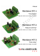
Manual Minitimer MT-1 k "Time Switch" tro ni Item 51-01015 | 51-01016 | 51-01017 el ek Minitimer MT-2 "Delayed switching" ta m s Item 51-01025 | 51-01026 | 51-01027 Minitimer MT-3 "Pulse delay" Item 51-01035 | 51-01036 | 51-01037 tams elektronik n n n
English MT-1 | MT-2 | MT-3 Contents Getting started............................................................................3 2. Safety instructions.......................................................................5 3. Safe and correct soldering...........................................................7 4. Operation overview.....................................................................9 5. Technical specifications..............................................................12 6.
MT-1 | MT-2 | MT-3 English 1. Getting started How to use this manual ni k This manual gives step-by-step instructions for safe and correct assembly of the kit and fitting and connecting of the ready-built module, and operation. Before you start, we advise you to read the whole manual, particularly the chapter on safety instructions and the checklist for trouble shooting. You will then know where to take care and how to prevent mistakes which take a lot of effort to correct.
English MT-1 | MT-2 | MT-3 Checking the package contents Required materials To assemble the kit you will need a soldering iron with temperature control and a thin tip and a deposit stand or a controlled soldering station a scraper, rag or sponge a heat-resistant pad a small pair of side cutters and wire strippers tweezers and flat-nose pliers if necessary electronic solder (preferably 0.5 to 0.
MT-1 | MT-2 | MT-3 English In order to connect the devices you possibly need a relay (see sections 8, 9 and 10): relay 12 V e.g. relay 1xUm 12 V, item no. 84-61010 MT-2 relay 5 V e.g. relay 2xUm 5 V, item no. 84-61020 and protective diode 1N4148, item no.83-11100 MT-3 relay 12 V e.g. relay 1xUm 12 V, Art.-Nr. 84-61010 ni Mechanical hazards tro 2. Safety instructions k MT-1 Cut wires can have sharp ends and can cause serious injuries. Watch out for sharp edges when you pick up the PCB.
English MT-1 | MT-2 | MT-3 Observe cable diameter requirements. After condensation build up, allow a minimum of 2 hours for dispersion. Use only original spare parts if you have to repair the kit or the ready-built module. Fire risk Thermal danger tro ni k Touching flammable material with a hot soldering iron can cause fire, which can result in injury or death through burns or suffocation. Connect your soldering iron or soldering station only when actually needed.
MT-1 | MT-2 | MT-3 ! English Caution: Little children can swallow small components with sharp edges, with fatal results! Do not allow components to reach small children. In schools, training centres, clubs and workshops, assembly must be supervised by qualified personnel. ! tro 3. Safe and correct soldering ni k In industrial institutions, health and safety regulations applying to electronic work must be adhered to.
English k ta m s el ek ni too much) solder simultaneously. As soon as the solder begins to flow, remove it from the soldering point. Then wait a moment for the solder to flow well before removing the soldering iron from the soldering joint. Do not move the component you have just soldered for about 5 seconds. A clean, non-oxidised (scale-free) soldering tip is essential for a perfect soldering joint and good soldering.
MT-1 | MT-2 | MT-3 English 4. Operation overview Minitimer MT-1 "Time Switch" k The minitimer MT-1 is designed for controlling operations in model railways which are supposed to last for 1 to 100 seconds. The desired switching time is set via a trimming potentiometer. ni Examples of use: Automatic opening of the gate at a level crossing after a certain time, automatic stop of trains at the platform for a certain time.
English MT-1 | MT-2 | MT-3 connection at the module´s input is shorter than the preset delay time, the connected device stays off. Devices with a current up to 100 mA intended to be switched on after a certain delay time can be connected directly to the minitimer´s output. Devices with a higher current or devices supposed to be switched off can be controlled via a relay.
MT-1 | MT-2 | MT-3 English Minitimer MT-1 ni k A = bridging the switching inputs B = voltage at the output U = voltage t = time Δt = on-time ta m s el ek tro Minitimer MT-2 A= B= U= t= Δt = voltage at the input voltage at the output voltage time switch-on delay Minitimer MT-3 A= B= U= t= Δt = voltage at the input voltage at the output voltage time delay time Seite 11
English MT-1 | MT-2 | MT-3 5. Technical specifications 12-18 Volt a.c. or d.c. voltage Current consumption (without connected devices) approx. 5 mA Max. current at the output MT-1: 100 mA MT-2: 100 mA MT-3: 1.000 mA Max. switching time (+ 20 %) MT-1: 100 seconds MT-2: 25 seconds MT-3: 60 seconds tro ni k Supply voltage IP 00 el ek Protected to 0 ... +60 °C Ambient temperature in storage -10 ... +80 °C Comparative humidity allowed max. 85 % Dimensions of the PCB (approx.
MT-1 | MT-2 | MT-3 English 6. Assembling the kit You can skip this part if you have purchased a ready-built module or device. Preparation Put the sorted components in front of you on your workbench. Resistors tro Resistors reduce current. ni k The separate electronic components have the following special features you should take into account in assembling: The value of resistors for smaller power ratings is indicated through colour rings. Every colour stands for another figure.
English MT-1 | MT-2 | MT-3 Trimm-potentiometers k Trimm-potentiometers (abrv. "trimm-pots") are resistors which allow the value of resistance to be varied and that way to be adapted to the particular demands. In the middle they have a small slot into which a small screwdriver can be put in order to vary the value of resistance. The maximum value is printed on the housing. tro Ceramic capacitors ni Depending on the mounting situation trimmpots with a lying or a standing package are used.
MT-1 | MT-2 | MT-3 English Diodes and Zener diodes Diodes allow the current to pass through in one direction only (forward direction), simultaneously the voltage is reduced by 0,3 to 0,8 V. Exceeding of the limit voltage always will destroy the diode, and allow current to flow in the reverse direction. Light emitting diodes (LEDs) tro The diode type is printed on the package. ni k Zener diodes are used for limiting voltages.
English MT-1 | MT-2 | MT-3 Integrated circuits (ICs) Depending on the type, ICs fulfil various tasks. The most common housing form is the so-called "DIL"-housing, from which 4, 6, 8, 14, 16, 18 or more "legs" (pins) are arranged along the long sides. tro Microcontrollers ni k ICs are sensitive to damage during soldering (heat, electrostatic charging). For that reason in the place of the ICs IC sockets are soldered in, in which the ICs are inserted later.
MT-1 | MT-2 | MT-3 English Resistors el ek tro ni k MT-1: PCB layout and parts list R1, R2, R3, R4 3,3 k R5, R6, R7 1 k R8 500 k Capacitors C4 100 nF Electrolytic capacitors C1, C2, C3 220 µF / 25 V Diodes D2, D3 1N400x, x=2...7 Zener diodes D1 5V1 Transistors Q1, Q2, Q3 BC547B Terminal strips X1 ...
English MT-1 | MT-2 | MT-3 R1 10 k R2 5,6 k R3 1 k R4, R5, R6 47 k Trim pots R7 500 k Diodes D1 1N400x, x=2...
MT-1 | MT-2 | MT-3 English Resistors el ek tro ni k MT-3: PCB layout and parts list R1, R2, R4, R6, R8 1 k 4,7 k R5 330 k Trim pots R7 500 k Diodes D1, D3, D4 1N4148 D5 1N400x, x=2...
English MT-1 | MT-2 | MT-3 Assembly Proceed according to the order given in the list below. First solder the components on the solder side of the PCB and then cut the excess wires with the side cutter. Follow the instructions on soldering in section 3. Caution: k ! tro ni Several components have to be mounted according to their polarity. When soldering these components the wrong way round, they can be damaged when you connect the power. In the worst case the whole circuit can be damaged.
MT-1 | MT-2 | MT-3 English Electrolytic capacitors Observe the polarity! One of the two leads (the shorter one) is marked with a minus sign. 7. Terminal strips Put together the terminal strips before mounting them. 8. Trimmpotentiometers The mounting orientation is preset by the layout of the three pins. 9. Light emitting diodes (LEDs) (MT-3 only) Observe the polarity! With wired LEDs the longer lead is always the anode (positive pole). ni tro Insert the ICs into the soldered socket.
English MT-1 | MT-2 | MT-3 7. Performing a functional test Set the trimm pot as follows: MT-2: middle position (= middle time delay) ni MT-1: left stop (= shortest possible switching time) k With all minitimers it is recommended to check function and switching times before mounting them. Proceed according to the sections 8. (MT1), 9. (MT-2) or 10. (MT-3), but connect a lamp to the outputs for the devices for the test.
MT-1 | MT-2 | MT-3 English 8. Connecting the MT-1 Follow the connections diagrams fig. MT-1.1 and MT-1.2 and connect the minitimer MT-1 as follows: X5 X6 X2 X4 device (polarized device "+") transformer (with direct voltage "^") k X3 device (polarized device "-") transformer (with direct voltage "+") switching input ni X1 ! Caution: el ek tro In order to trigger the minitimer MT-1 the switching input (connections X5 and X6) has to be shunted, e.g. with a key switch.
English MT-1 | MT-2 | MT-3 ta m s el ek tro ni k Fig. MT-1.
MT-1 | MT-2 | MT-3 English ta m s el ek tro ni k Fig. MT-1.
English MT-1 | MT-2 | MT-3 9. Connecting the MT-2 Follow the connections diagrams fig. MT-2.1 and MT-2.2 and connect the minitimer MT-2 as follows: X1-2 device (polarized device "-") X2-3 transformer / earth (with direct voltage "^") k X2-1 X2-2 device (polarized device "+") switching input transformer (with direct voltage "+") ni X1-1 el ek tro In order to trigger the minitimer MT-2 you have to connect the switching input (connection X2-1) to earth (connection X2-3), e.g. with a switch.
MT-1 | MT-2 | MT-3 English ta m s el ek tro ni k Fig. MT-2.
English MT-1 | MT-2 | MT-3 ta m s el ek tro ni k Fig. MT-2.
MT-1 | MT-2 | MT-3 English 10. Connecting the MT-3 Follow the connections diagrams fig. MT-3.1 and MT-3.2 and connect the minitimer MT-3 as follows: device (polarized device "+") X1-2 device (polarized device "-") Remark: You can connect solenoid articles directly to the output.
English MT-1 | MT-2 | MT-3 ta m s el ek tro ni k Fig. MT-3.
MT-1 | MT-2 | MT-3 English ta m s el ek tro ni k Fig. MT-3.
English MT-1 | MT-2 | MT-3 11. Check list for troubleshooting Parts are getting too hot and/or start to smoke. ! Disconnect the system from the mains immediately! tro ni k Possible cause: one or more components are soldered incorrectly. à In case you have mounted the module from a kit, perform a visual check (à section 6.) and if necessary, remedy the faults. Otherwise send in the module for repair. The lamp connected for the functional test of the module does not light.
MT-1 | MT-2 | MT-3 English Hotline: If problems with your module occur, our hotline is pleased to help you (mail address on the last page). ni k Repairs: You can send in a defective module for repair (address on the last page). In case of guarantee the repair is free of charge for you. With damages not covered by guarantee, the maximum fee for the repair is the difference between the price for the ready-built module and the kit according to our valid price list.
English MT-1 | MT-2 | MT-3 12. Guarantee bond ni k For this product we issue voluntarily a guarantee of 2 years from the date of purchase by the first customer, but in maximum 3 years after the end of series production. The first customer is the consumer first purchasing the product from us, a dealer or another natural or juristic person reselling or mounting the product on the basis of selfemployment.
MT-1 | MT-2 | MT-3 English 13. EU Declaration of Conformity This product fulfils the requirements of the following EU directives and therefore bears the CE marking. 2001/95/EU Product Safety Directive compatibility (EMC Directive).
n n n tro http://www.tams-online.de n ni Information and tips: k n n el ek n n n s Warranty and service: ta m Tams Elektronik GmbH Fuhrberger Straße 4 DE-30625 Hannover fon: +49 (0)511 / 55 60 60 fax: +49 (0)511 / 55 61 61 e-mail: modellbahn@tams-online.