
Instructions
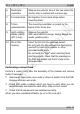
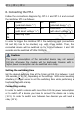
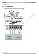
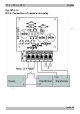
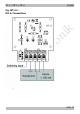
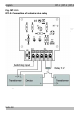
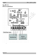
Table Of Contents
- 1. Getting started
- 2. Safety instructions
- 3. Safe and correct soldering
- 4. Operation overview
- 5. Technical specifications
- 6. Assembling the kit
- 7. Performing a functional test
- 8. Connecting the MT-1
- 9. Connecting the MT-2
- 10. Connecting the MT-3
- 11. Check list for troubleshooting
- 12. Guarantee bond
- 13. EU Declaration of Conformity
- 14. Declarations concerning the WEEE directive

tams elektronik
MT-1 | MT-2 | MT-3 English
10. Connecting the MT-3
Follow the connections diagrams fig. MT-3.1 and MT-3.2 and connect
the minitimer MT-3 as follows:
X1-1 device
(polarized device "+")
X1-2 device
(polarized device "-")
Remark: You can connect solenoid articles directly to the output.
X2-1 transformer / earth
(with direct voltage "^")
X2-2 transformer
(with direct voltage "+")
X2-3 switching input
After applying the voltage, the LED on the module will not be switched
on before the set delay time has passed, in order to check the set time
delay. After the set time has elapsed, the minitimer is operational,
indicated by the LED permanently lighting.
As a rule, the minitimer MT-3 is switched in series with other electronic
circuits generating voltage changes at it´s input (changes between
open and closed ground connection between the switching input X2-3
and the ground connection X2-1). The connected device will be
switched on and off to the rhythm of the voltage changes, however
with the set time delay.
Setting the time delay
Set the desired delay time at the trimm pot R7. Turning to the left will
increase the delay time.
Please note: When altering the time delay during operation without
disconnecting the module from the power supply, first all saved voltage
changes will be "worked off" before the new set time delay takes effect.
Connecting a relay
In order to switch a device with more than 1.000 mA power
consumption or to invert the signals you have to connect the device via
a relay (12 V).
Seite 29