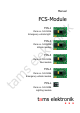
Manual FCS-1 ni Item no. 54-01016 Emergency vehicle light k FCS-Module tro FCS-2 el ek Item no. 54-01026 Vehicle module FCS-3 ta m s Item no. 54-01036 Bus module FCS-4 Item no. 54-01046 Emergency vehicle module FCS-L Item no.
FCS modules s el ek tro ni k English ta m © 10/2017 Tams Elektronik GmbH All rights reserved. No part of this publication may be reproduced or transmitted in any form or by any means, electronic or mechanical, including photocopying, without prior permission in writing from Tams Elektronik GmbH. Subject to technical modification. ** Faller is a registered and protected trade mark of Gebrueder Faller GmbH, Guetenbach, Germany.
FCS modules English Table of contents Getting started............................................................................4 2. Safety instructions.......................................................................6 3. Safe and correct soldering...........................................................9 4. Operation overview...................................................................10 7. Possible connections.........................................................10 4.3.
English FCS modules 1. Getting started This manual applies to the following FCS modules compatible to the Faller** Car System, so for: How to use this manual tro ni k FCS-1 "Emergency vehicle light" FCS-2 "Vehicle module" FCS-3 "Bus module" FCS-4 "Emergency vehicle module" FCS-L "Lighting module" Provided there are no other details given for particular sections, the information given applies to all modules.
FCS modules English Checking the package contents Please make sure that your package contains: Module Additional components manual* FCS-1 1 --- 1 FCS-2 1 2 1 1 1 1 1 1 resistors 10 W resistor 10 kW light sensitive resistor diode 1N4148 transistor BC 327 reed contact dim switch DS-1 FCS-3 1 1 1 1 1 resistor 10 kW diode 1N4148 transistor BC 327 reed contact 1 FCS-4 1 1 1 2 1 resistor 10 kW diode 1N4148 transistors BC 327 loudspeaker 1 FCS-L 1 el ek tro ni k 1 1 ta m s 1 diode
English k 2. Safety instructions Mechanical hazards ni electronic tin solder (0.5 mm diameter) connecting wire, e.g. enamelled copper wire LEDs for the vehicle´s lighting.
FCS modules Connect transformers and soldering irons only in approved mains sockets installed by an authorised electrician. Observe cable diameter requirements. After condensation build up, allow a minimum of 2 hours for dispersion. Use only original spare parts if you have to repair the kit or the ready-built module. k English ni Fire risk el ek tro Touching flammable material with a hot soldering iron can cause fire, which can result in injury or death through burns or suffocation.
English FCS modules Other dangers Children can cause any of the accidents mentioned above because they are inattentive and not responsible enough. Children under the age of 14 should not be allowed to work with this kit or the ready-built module. Caution: k ! ni Little children can swallow small components with sharp edges, with fatal results! Do not allow components to reach small children. tro In schools, training centres, clubs and workshops, assembly must be supervised by qualified personnel.
FCS modules English 3. Safe and correct soldering ! Caution: ni tro ta m el ek Use a small soldering iron with max. 30 Watt. Keep the soldering tip clean so the heat of the soldering iron is applied to the solder point effectively. Only use electronic tin solder with flux. When soldering electronic circuits never use soldering-water or soldering grease. They contain acids that can corrode components and copper tracks.
English FCS modules 4. Operation overview ni 4.1. Voltage supply k The modules are particularly designed for the use in vehicles compatible to the Faller** car system. The modules FCS-1 to FCS-4 are used in vehicles run with two accumulator batteries, the module FCS-L in vehicles with one accumulator battery or, when reducing the module´s input voltage, in vehicles run with two accumulator batteries, as well.
English FCS-2 FCS-3 FCS-4 FCS-L Front lights (white LEDs) + + + + + Back lights (red LEDs) + + + + + Brake lights - + + + - Dim switch DS-1 - + - - - + (5) - - + (2) - Warning lights (yellow LEDs) - - - - Siren (loudspeaker) - - - + - Motor / acceleration delay - + + + - Motor / braking delay - + + - - Front lights ni el ek Flashing lights (blue or orange LEDs) k FCS-1 tro FCS modules + All modules offer the possibiliy to connect white LEDs
English FCS modules Dim switch (FCS-2 only) Depending on the ambient lighting, the lighting of the vehicle is switched on and off via a light sensitive switch. The sensitivity of the switch is set via a trimpot. Flashing lights (FCS-1 and FCS-4) Warning lights (FCS-3 only) ni k The FCS-1 has 5 outputs, the FCS-4 two outputs for the connection of orange or blue LEDs as flashing lights.
FCS modules English 4.3. Modes of operation FCS-1 "Emergency vehicle light" According to the connection of the circuit´s input, the LEDs connected to the five outputs are controlled by two different programmes: ni k Programme 1 "Double flashlight": The LEDs flash twice each and then go out for a short time. The LEDs connected to two of the five outputs double flash alternately. The other three outputs generate an asynchronous double flash which is interrupted by different intervals.
English FCS modules FCS-4 "Emergency vehicle module" ta m s el ek tro ni k While the vehicle is in motion the flashing lights double flash and the siren is in operation with short breaks. When crossing a stop the back lights are switched brighter for a short time as braking lights and the siren is switched off (provided the reed contact which is in the vehicle is connected to the module). As long as the vehicle is in operation the flashing lights are switched on.
FCS modules English 5. Technical specifications 5.1. FCS-1 to FCS-4 2 - 3 Volt d.c. voltage Current consumption (without connected loads) approx. 2 mA Max. total current 40 mA Total number of outputs Max. current per output max. 6 (depending on the version) 10 mA tro ni k Supply voltage 1 Protected to IP 00 el ek FCS-4 only: output for loudspeaker 0 ... +60 °C Ambient temperature in storage -10 ... +80 °C Comparative humidity allowed max. 85 % Dimensions of PCB approx. 12 x 18 x 2.
English FCS modules 5.2. FCS-L Supply voltage - vehicles with one battery - vehicles with two batteries 0,9 – 1,8 Volt d.c. voltage 1,6 – 2,5 Volt d.c. voltage Current consumption ca. 25 mA Protected to IP 00 Ambient temperature in use Ambient temperature in storage 0 ... +60 °C -10 ... +80 °C max. 85 % el ek Comparative humidity allowed ni 1 25 mA tro Total number of outputs Max. current per output k (independent of the voltage applied) approx. 4,2 x 7,4 x 1.7 mm Weight of PCB approx.
FCS modules English 6. Special features of the additional components Depending on the specification of the modules, different additional external components have to be connected. These have the following special features: k Resistors Colour rings brown - black - black (gold) brown - black - orange (gold) el ek Value 10 W 10 kW tro ni Resistors reduce current. Their mounting orientation is of no importance. The value of resistors for smaller power ratings is indicated through colour rings.
English FCS modules Diodes k Diodes allow the current to pass through in one direction only (forward direction), simultaneously the voltage is reduced by 0,3 to 0,8 V. Exceeding of the limit voltage always will destroy the diode, and allow current to flow in the reverse direction. The diode type is printed on the package. tro Light emitting diodes (LEDs) ni Diodes must be mounted in a given direction. The negative end is marked with a ring.
FCS modules English Transistors Transistors are current amplifiers which convert low signals into stronger ones. There are several types in different package forms available. The type designation is printed on the component. tro Reed contacts (SRK) ni k Transistors for a low power rating (e.g. BC types) have a package in form of a half zylinder (SOT-package). The three pins of bipolar transistors (e.g.
English FCS modules 7. Mounting 7.1. Mounting the FCS-1 el ek Connections FCS-1 tro ni k Open the housing of the vehicle. Locate the position for the module.. Connection to the supply voltage "+" of the batteries ta m X2 "-" of the batteries s X1 ! Caution: The module should not be connected the wrong way round.
FCS modules English Connection of the LEDs for the flashlights Connect the anodes (+) of the LEDs to the soldering points X4 to X8 and the cathodes (-) to the soldering point X3. Note the different functions of the outputs. Additional series resistors are not necessary for the operation of the LEDs for the flashlights. ni k When you want to run program 2 ("Alternating flashlight") you have to make a connection between the soldering points X9 and X3.
English FCS modules Connection of the LEDs for the front light X2 el ek tro ni k You may connect up to two white LEDs for the front lighting to the module. LED6* | LED7* R6* | R7* X3 White LEDs for front lighting Series resistors for LED6 and LED7 Voltage output (-) of the circuit s * Not supplied. ta m ! Caution: The LEDs for the front lighting must be operated via series resistors (recommended value: 100 ). Otherwise the connected LEDs are damaged and the circuit may not work as intended.
FCS modules English ni tro ta m s el ek Open the housing of the vehicle. Locate the position for the module. Disconnect all connections from the accumulator batteries, the motor and the mounted reed contact except for the wire to the charging contact. k 7.2. Mounting the FCS-2 Connections FCS-2 n many vehicles the resistor R7 shown in the connection diagram is mounted into the lead-in wire to the motor.
English FCS modules "-" of the batteries "+" of the batteries X3 Voltage output (-) of the circuit X4 Front lighting (LED1 and LED2) X5 Light sensitive switch X6 Braking / reversing lights (LED3 and LED4) X7 Motor control X8 Existing reed contact X9 Secondary reed contact D2 (1N4148) ni Additional diode Existing batterries LED1*, LED2* LED3*, LED4* DS-1 el ek G1, G2 tro External Components k X1 X2 White LEDs for front lighting Red LEDs for braking and reversing lights Dim switch
FCS modules English Connection to the supply voltage Connect the connecting point X2 to the plus pole of the accumulator batteries and the minus pole of the accumulator batteries to the existing switch S of the vehicle. Connect the second pole of the switch to the connecting point X1. Connection of the existing reed contact ni k ! Caution: The module should not be connected the wrong way round.
English FCS modules Connection of the motor tro Connection of the dim switch ni k Connect the enclosed diode 1N4148 to the connections of the motor. Observe the polarity of the diode. Then connect the minus pole of the motor to the switch switching the minus pole of the accumulator batteries and to the connecting point X1. Next connect the collector (C) of the enclosed transistor BC 327 to the plus pole of the motor, the basis (B) to the connecting point X7 and the emitter (E) to the resistor R7.
FCS modules English Setting the sensitivity of the light ta m s el ek tro ni k Before closing the housing of the vehicle, you should set the sensitivity of the dim switch to the desired lighting conditions. First set the trim pot to mid-position and change the sensitivity as far as necessary. The circuit requires 3 or 4 seconds to react.
English FCS modules 7.3. Mounting the FCS-3 ni k Open the housing of the vehicle. Locate the position for the module. Disconnect all connections from the accumulator batteries, the motor and the mounted reed contact except for the wire to the charging contact. ta m s el ek tro Connectsions FCS-3 In many vehicles the resistor R7 shown in the connection diagram is mounted into the lead-in wire to the motor.
FCS modules English "-" of the batteries "+" of the batteries / LED1 and LED4 X3 Voltage output (-) of the circuit X4 Motor control X5 Right indicator (LED3 and LED4) X6 Braking / reversing lights (LED5 and LED6) X7 Left indicator (LED7 and LED8) X8 Existing reed contact X9 Additional reed contact D2 (1N4148) ni Existing batterries LED1*, LED2* LED3*, LED4* LED5*, LED6* White LEDs for front lighthing Yellow LEDs fort he right indicator Red LEDs for braking and reversing lights Yellow LED
English FCS modules Connection to the supply voltage Connect the connecting point X2 to the plus pole of the accumulator batteries and the minus pole of the accumulator batteries to the existing switch S of the vehicle. Connect the second pole of the switch to the connecting point X1. Connection of the existing reed contact ni k ! Caution: The module should not be connected the wrong way round.
FCS modules English Connection of the motor ni k Connect the enclosed diode 1N4148 to the connections of the motor. Observe the polarity of the diode. Then connect the minus pole of the motor to the switch switching the minus pole of the accumulator batteries and to the connecting point X1. Next connect the collector (C) of the enclosed transistor BC 327 to the plus pole of the motor, the basis (B) to the connecting point X4 and the emitter (E) to the resistor R7.
English FCS modules Connection of the LEDs for the front light You may connect up to two white LEDs for the front lighting to the voltage output of the module. These LEDs are not controlled by the stored software. They light as soon as the module is connected to the power supply. k Connect the anodes (+) of the LEDs to the soldering point X2 and the cathodes (-) to the soldering point X3.
FCS modules English 7.4. Mounting the FCS-4 ni k Open the housing of the vehicle. Locate the position for the module. Disconnect all connections from the accumulator batteries, the motor and the mounted reed contact except for the wire to the charging contact. ta m s el ek tro Connections FCS-4 In many vehicles the resistor R7 shown in the connection diagram is mounted into the lead-in wire to the motor.
English FCS modules "-" of the batteries "+" of the batteries / LED1 and LED2 X3 Voltage output (-) of the circuit X4 Flashing light 1 (LED3) X5 Flashing light 2 (LED4) X6 Siren X7 Motor control X8 Braking / reversing lights (LED5 and LED6) X9 Existing reed contact D2 (1N4148) ni Additional diode Existing batterries LED1*, LED2* LED3*, LED4* LED5*, LED6* M el ek G1, G2 tro External Components k X1 X2 White LEDs for front lighthing Blue LEDs for flashing lights Red LEDs for brakin
FCS modules English Connection to the supply voltage Connect the connecting point X2 to the plus pole of the accumulator batteries and the minus pole of the accumulator batteries to the existing switch S of the vehicle. Connect the second pole of the switch to the connecting point X1. Connection of the existing reed contact ni k ! Caution: The module should not be connected the wrong way round.
English FCS modules Connection of the LEDs for the flashing lights Connect the anodes (+) of the two LEDs for the flashing lights to the connecting points X4 and X5. Connect the cathodes (-) of the LEDs both to the connecting point X3. Additional series resistors are not necessary for the operation of the LEDs for the flashing lights. k Connection of the LEDs for the stop and back lights tro ni The two LEDs for the stop and back lights have to be connected in series, i.e.
FCS modules English Connection of the diodes for the front light You may connect up to two white LEDs for the front lighting to the voltage output of the module. These LEDs are not controlled by the stored software. They light as soon as the module is connected to the power supply. k Connect the anodes (+) of the LEDs to the soldering point X2 and the cathodes (-) to the soldering point X3.
English FCS modules 7.5. Mounting the FCS-L Connections FCS-L tro ni k Open the housing of the vehicle. Locate the position for the module. LED, white (not supplied) D3, D4 LED, red (not supplied) D5 if required, e.g.
FCS modules English Connection to the supply voltage The module is designed for connecting to a supply voltage of 0,9 to 1,8 V (= one accumulator battery). If it is connected to a higher supply voltage of 1,6 bis 2,5 V (= two accumulator batteries) you have to reduce the input voltage by mounting a diode (e.g. 1N4148) in the lead-in wire. ni k Connect the soldering point X1 to the positive pole and the soldering point X2 to the negative pole of the accumulator batteries.
English FCS modules 8. Check list for troubleshooting Parts are getting very hot and/or start to smoke. ! Disconnect the system from the mains immediately! ni The LEDs do not light / flash. Possible cause: The LEDs are connected the wrong round. à Check the connections. tro k Possible cause: The connections to the power supply are connected the wrong round. à Check the connection. In this case the module is probably damaged irreparably. Possible cause: The power supply is interrupted.
FCS modules English FCS-4: The siren does not work. Possible cause: The connections of the transistor are reversed. à Check the connections. Possible cause: The power supply is interrupted. à Check the connections. ni k Possible cause: The vehicle halts at a stop. This is no a fault. The siren is switched off while the vehicle is halting. tro Hotline: If problems with your module occur, our hotline is pleased to help you (mail address on the last page).
English FCS modules 9. Guarantee bond ni k For this product we issue voluntarily a guarantee of 2 years from the date of purchase by the first customer, but in maximum 3 years after the end of series production. The first customer is the consumer first purchasing the product from us, a dealer or another natural or juristic person reselling or mounting the product on the basis of selfemployment.
FCS modules English 10. EU declaration of conformity This product conforms with the EC-directives mentioned below and is therefore CE certified. ni Connect the transformer only to an approved mains socket installed by an authorised electrician. Make no changes to the original parts and accurately follow the instructions, connection diagrams and PCB layout included with this manual. Use only original spare parts for repairs. tro k 2004/108/EG on electromagnetic.
n n n tro http://www.tams-online.de n ni Information and tips: k n n el ek n n n s Warranty and service: ta m Tams Elektronik GmbH Fuhrberger Straße 4 DE-30625 Hannover fon: +49 (0)511 / 55 60 60 fax: +49 (0)511 / 55 61 61 e-mail: modellbahn@tams-online.