k Manual ni Booster B-4 ta m s el ek tro Item no.
English Booster B-4 Table of contents Why Boosters?............................................................................3 2. Getting started............................................................................4 3. Safety instructions.......................................................................6 4. Your B-4.....................................................................................7 5. Splitting your model railway layout.............................................
Booster B-4 English 1. Why Boosters? The three essential functions of boosters are: 1. Supplying the power needed for the operation of digital controlled locomotives and points and other digital consumers. ni k 2. Bringing the voltage to the rails, in order to make sure that all vehicle and accessory decoders receive the digital switching and control commands. tro 3. Making sure the current is switched off in case of a short-circuit on the layout (e.g.
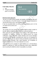
English Booster B-4 2. Getting started How to use this manual ni k This manual gives step-by-step instructions for safe and correct connecting of the booster, and operation. Before you start, we advise you to read the whole manual, particularly the chapter on safety instructions and the checklist for trouble shooting. You will then know where to take care and how to prevent mistakes which take a lot of effort to correct. tro Keep this manual safely so that you can solve problems in the future.
Booster B-4 English Required materials In order to connect the booster you need: Wire. Recommended diameter: for the connection to the transformer and the rails: > 1,5 mm² for the connection to the digital control unit: > 0,25 mm² k A transformer. The recommended voltage and the minimum power of the transformer depend on the desired settings.
English Booster B-4 3. Safety instructions Risk of electric shock ni k ! Risk of fire The booster is cooled by a ventilating fan to prevent overheating. Thus be careful to allow the air to flow unhindered through the ventilation slits at the booster´s top and back surface. If the vents are blocked components can overheat and catch fire.
Booster B-4 English 4. Your B-4 Technical specifications 12 – 20 V AC voltage 12 – 26 V DC voltage Maximum output current 2, 3, 4 or 5 A Output voltage 10 – 24 volts digital voltage Power max. 120 Watt Digital formats DCC, Motorola, mfx (control commands only) ni tro Feedback log Track signal Protected to RailCom DCC-conforming booster port (3-pole) el ek Interface k Supply voltage symmetrical IP 00 s Ambient temperature in use ta m Ambient temperature in storage 0 ...
English Booster B-4 Front side of the B-4 LED 7- segment display (item no. 40-19417) Data formats and ports ni k 1 2 tro The B-4 is a multi protocol booster and capable of amplifying data sent in the Motorola or the DCC format. It transmits control commands in mfx-format as well, but no mfx feedback signals. RailCom el ek It can be connected either to a DCC-conforming booster port or to the rail output of the control unit.
Booster B-4 English Using the ABC-braking method The booster amplifies the track signal completely symmetrically. This allows the ABC-braking method to be used in DCC-controlled layouts. The DCC-input of the booster B-4 is isolated through an opto-coupler. Balanced track voltage ni k The booster B-4 provides a regulated track voltage, which can be set to a value between 10 and 24 V in 1 V-steps. At delivery the track voltage is set to 18 V.
English Booster B-4 Rated size Recommended short circuit sensivity (= interrupting current) Z and N 2A TT and H0 3A 0, I and II >4A Value in state of delivery k 5A el ek tro ni ! Please note: The set short circuit sensitivity should not exceed the maximum transformer´s current.
Booster B-4 English Short circuit warning As a basis for a PC controlled booster management the B-4 can send a short circuit warning when a limiting value underneath the set interrupting current is exceeded. The PC control can switch off carriage lighting in an overloaded booster section then, for example, when a short circuit due to overload is imminent. tro ni k The limiting value for the short circuit warning can be set from a value 0 to 1.0 A below the set interrupting current.
English Booster B-4 Switching on and off the B-4 with a DCC points switching command The B-4 can be switched on and off via a a DCC point switching command sent to an assigned points address.
Booster B-4 English 5. Splitting your model railway layout ni station engine sheds the main lines (if necessary in several sections) the branch lines (if necessary in several sections) tro k Split your model railway layout in several track sections electrically isolating them from each other. Every section has to be supplied by a booster of its’ own. In each section a maximum of three to five locomotives should run at the same time.
English Booster B-4 ta m tro s Connections el ek Connections control unit E Short circuit report wire D Ground C Data ni k 6.
Booster B-4 English In order to connect the cables to the booster use the enclosed connectors which are designed to screw on the cables. ni k ! Please note: Do not block the flow of air through the ventilation slits at the booster ´s top and back surface, otherwise the booster can overheat. Risk of fire! You should never cover the ventilation slits. When connecting the booster be sure to keep sufficient distance to other devices, walls, and the like.
English Booster B-4 Connecting the tracks k Connect the booster´s track port to both rails (with 2-rail systems) or to one rail and the middle conductor (with 3-rail systems). These connections should be repeated every 2-3 meters, because the resistance at the connection points of the tracks is quite high. When choosing too high intervals, problems with the short circuit indication or the power supply of the vehicles may occur.
Booster B-4 English 7. Settings The booster B-4 can be set to individual requirements by programming on main (POM) or by inserting short-circuit terminations (jumpers). Manufacturers settings Setting with jumpers Track voltage 10 – 24 V, to be set in 1 V-steps 18 V yes, 16 – 22 V Autostarting time after a short circuit 4 – 10 Sek., to be set in 1 sec.-steps Max. track current (interrupting current after a short circuit) RailCom ni k Possible settings 4 sec.or 10 sec.
English Booster B-4 7.1. Programming the B-4 The booster B-4 is set by programming on main (POM). This is possible only with control units supporting this programming mode. ni k In order to start programming the booster, input the value "62" for CV#7 of any DCC locomotive address. Proceed as described in the manual of your control unit. This input has no effect on a decoder with the chosen address, as locomotive decoders do not allow setting a value for CV#7 (= version).
Booster B-4 English Value for CV#7 Settings / Remarks Reset 8 Reset. Sets the values back to the default values. Track voltage (output value) Default value: 18 V 10 10 volts 11 11 volts 13 ... 23 volts 24 24 volts 34 4 seconds 36 ... tro 35 ni 12 volts ... 5 seconds 6 seconds 7 ... 9 seconds el ek Autostarting time after a short circuit Default value: 4 sec. 12 k Function 40 10 seconds 42 2 amperes 43 3 amperes 44 4 amperes 45 5 amperes RailCom.
English Booster B-4 Value Settings / Remarks for CV#7 Watchdog Default value: inactive 74 active 75 inactive 76 Change over into the programming mode. k Function 0A Hint: The short circuit warning will be sent, when the set interrupting current less the value is exceeded.
Booster B-4 English 7.2. Setting the B-4 with jumpers With control units not supporting programming on main (POM) the booster B-4 can be set by inserting short-circuit terminations (jumpers). Please note: It is not possible to set the whole range of values by inserting jumpers. tro ni k Before inserting the jumpers you have to open the booster´s housing.
English Booster B-4 Settings JP1 inserted, JP2 open Track voltage = 16 volts JP1 + JP2 open Track voltage = 18 volts (in state of delivery) or the last set value JP2 inserted, JP1 open Track voltage = 20 volts JP1 + JP2 inserted Track voltage = 22 volts JP3 + JP4 inserted Max. track current (interrupting current) = 2 amperes JP3 inserted, JP 4 open Max. track current (interrupting current) = 3 amperes JP4 inserted, JP3 open Max.
Booster B-4 English 8. Operation Shunting the boundry between two booster sections ni k You should take care not to allow locomotives or trains to halt directly on the boundary between two sections. This would lead to a connection between the outputs and possible damaging of the two connected boosters. The short circuit indication does not work under these circumstances. LED LED tro The LED on the front lights or flashes indicating the operation modes or problems that occur.
English Booster B-4 Display In the version art.-no. 40-19417 the booster B-4 has a two-digit 7segment display. During operation it shows the present current [A]. After a short circuit the remining seconds till the re-switching on are displayed. In addition, the display shows the following operating status: Meaning −− −− The watchdog has been released and the booster has been switched off in consequence. k Display −− −− tro ni The booster has been switched off by a points switching command.
Booster B-4 English 9. Check list for troubleshooting The booster is getting very hot and/or starts to smoke. ! Disconnect the system from the mains immediately! The LED at the booster does not light and the locomotives cannot be driven. ni k Possible reason: The connections to the track and the power supply have been mixed up. à Alter the connections. Possibly the booster has been damaged. tro Possible reason: The power supply has been interrupted.
English Booster B-4 autostarting time automatically on again. In case the short circuit is still there after autostarting, the booster switches off immediately. This procedure is repeated five times, followed by a one minute break. à Eliminate the short circuit. The watchdog function is not active after switching on the booster although it has been set active. After a points switching command the booster has been switched off, the LED flashes yellow.
Booster B-4 English Hotline: If problems with your device occur, our hotline is pleased to help you (mail address on the last page). k Repairs: You can send in a defective device for repair (address on the last page). In case of guarantee the repair is free of charge for you. With damages not covered by guarantee, the maximum fee for the repair is 50 % of the sales price according to our valid price list.
English Booster B-4 10. Guarantee bond ni k For this product we issue voluntarily a guarantee of 2 years from the date of purchase by the first customer, but in maximum 3 years after the end of series production. The first customer is the consumer first purchasing the product from us, a dealer or another natural or juristic person reselling or mounting the product on the basis of selfemployment.
Booster B-4 English 11. EU declaration of conformity This product conforms with the EC-directives mentioned below and is therefore CE certified. k 2004/108/EG on electromagnetic. Underlying standards: EN 55014-1 and EN 61000-6-3. To guarantee the electromagnetic tolerance in operation you must take the following precautions: Connect the transformer only to an approved mains socket installed by an authorised electrician.
Booster B-4 ta m s el ek tro ni k English Page 30
English ta m s el ek tro ni k Booster B-4 Page 31
n n n tro http://www.tams-online.de n ni Information and tips: k n n el ek n n n s Warranty and service: ta m Tams Elektronik GmbH Fuhrberger Straße 4 DE-30625 Hannover fon: +49 (0)511 / 55 60 60 fax: +49 (0)511 / 55 61 61 n n n e-mail: modellbahn@tams-online.