
User manual

tams elektronik
English KSM-3
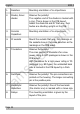
1. Resistors Mounting orientation of no importance.
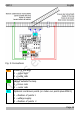
2. Diodes, Zener
diodes
Observe the polarity!
The negative end of the diodes is marked with
a ring. This is shown in the PCB layout.
Solder the diode D6 and D7 that way, their
bodies are standing upright on the PCB.
3. Ceramic
Capacitors
Mounting orientation of no importance.
4. IC sockets Mount the sockets that way, the markings on
the sockets show in the same direction as the
markings on the PCB board.
5. Transistors Observe the polarity!
The cross section of transistors for a low
power rating in SOT-packages is shown in the
PCB layout.
With transistors for a high power rating in TO
packages (e.g. BD types) the unlabelled back
side is marked in the PCB layout by a thick
line.
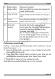
6. Rectifiers Observe the polarity! The pin connections are
printed on the housing. The longer connecting
pin is the positive pole.
7. Electrolytic
capacitors
Observe the polarity! One of the two leads
(the shorter one) is marked with a minus sign.
8. Relays The mounting orientation is given by the
layout of the pins.
Page 22