mfx®-Adapter für Booster ni mfx® adapter for booster k Booster-Link tro mfx®-adapter voor boosters ta m s el ek Adaptateur mfx® pour Anleitung Manual Mode d´emploi Handleiding Art.-Nr.
© 01/2016 Tams Elektronik GmbH Alle Rechte, insbesondere das Recht der Vervielfältigung und Verbreitung sowie der Übersetzung vorbehalten. Vervielfältigungen und Reproduktionen in jeglicher Form bedürfen der schriftlichen Genehmigung durch die Tams Elektronik GmbH. Technische Änderungen vorbehalten. Deutsch 3 17 Français 31 k English ni Nederlands 45 el ek tro © 01/2016 Tams Elektronik GmbH All rights reserved.
Booster-Link English Table of contents 18 2. Safety instructions 19 3. Safe and correct soldering 21 4. Operation overview 23 5. Technical specifications 23 6. Assembling the Booster-Link 24 7. Connecting the Booster-Link 28 8. Check list for troubleshooting 28 9. CE and Warranty 29 tro ni k 1. Getting started Parts list I II Circuit diagram (fig. 2) II el ek Printed Circuit Board (PCB) layout (fig. 1) Connections diagram (fig.
English Booster-Link 1. Getting started How to use this manual This manual gives step-by-step instructions for safe and correct assembly of the kit and fitting and connecting of the ready-built module, and operation. Before you start, we advise you to read the whole manual, particularly the chapter on safety instructions and the FAQ chapter. You will then know where to take care and how to prevent mistakes which take a lot of effort to correct.
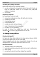
Booster-Link English Checking the package contents Please make sure that your package contains: one kit, containing the components listed in the parts list and one PCB, one ready-built module or one complete unit (ready-built module in a housing), one manual. Required materials For assembling the kit you need: s el ek tro ni k an electronic soldering iron (max.
English Booster-Link impermissibly high humidity, condensation build up can cause serious injury due to electrical shock. Take the following precautions to prevent this danger: Never perform wiring on a powered module. Assembling and mounting the kit should only be done in closed, k ni tro el ek clean, dry rooms. Beware of humidity. Only use low power for this module as described in this manual and only use certified transformers.
Booster-Link English Dangerous environments A working area that is too small or cramped is unsuitable and can cause accidents, fires and injury. Prevent this by working in a clean, dry room with enough freedom of movement. Other dangers Children can cause any of the accidents mentioned above because they are inattentive and not responsible enough. Children under the age of 14 should not be allowed to work with this kit or the ready-built module.
English Booster-Link Observe correct polarity orientation of semi-conductors, LEDs tro ta m s el ek ni k electrolytic capacitors and integrated circuits before soldering and ensure that the solder time does not exceed 5 seconds, otherwise components can be damaged. Apply the soldering tip to the soldering spot in such a way that the part and the soldering eye are heated at the same time. Simultaneously add solder (not too much). As soon as the solder becomes liquid take it away.
Booster-Link English 4. Operation overview Standard boosters used in digital model railway layouts controlled by mfx®-central units (e.g. mobile station or central station of Maerklin**), do not allow the transfer of the mfx®-feed back data across the isolation between the booster sections. For that reason vehicles that are in booster sections supplied by standard boosters cannot log in at the central unit.
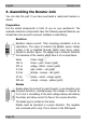
English Booster-Link 6. Assembling the Booster-Link You can skip this part if you have purchased a ready-built module or device. Preparation Put the sorted components in front of you on your workbench.
Booster-Link English Zener diodes Zener diodes are used for limiting voltages. In contrast to "normal" diodes they are not destroyed when the limit voltage is exceeded. Capacitors el ek Electrolytic capacitors ni Number 102 104 tro Value 1 nF 100 nF k Among other things capacitors are used for filtering interference voltages or as frequency determining parts. Ceramic capacitors are not polarized, for that reason their mounting orientation is of no importance.
English Booster-Link Integrated circuits (ICs) Depending on the type, ICs fulfil various tasks. They are polarized and therefore have to be mounted in a certain direction. The most common housing form is the so-called "DIL"-housing, from which 4, 6, 8, 14, 16, 18 or more "legs" (pins) are arranged along the long sides. The mounting orientation is shown by a semicircular or circular marking at the end of the housing, which is also shown on the PCB layout.
Booster-Link ! English Caution: Diodes, ICs, electrolytic capacitors and transistors must be placed in the right direction! If you solder them the wrong way the affected parts can be damaged when you connect the power supply. In the worst case the whole circuit can be damaged. In any case, a wrongly connected part will not function. Finally, solder in the terminal strip and insert the ICs into the soldered IC-socket.
English Booster-Link 7. Connecting the Booster-Link Required number of Booster-Links For each external booster supplying the mfx® layout you need one Booster-Link. In case one external booster supplies several booster sections one Booster-Link is sufficient. Performing the booster sectionings k Isolate the centre conductor at the sectioning between the booster sections (if not already done). Please note: The outer conductors must not be isolated.
Booster-Link English Possible Cause: The decoder does not send the mfx® feed back data to the central unit. Check the decoder by setting the vehicle on to a rail section supplied by the booster integrated into the mfx® central unit. Hotline If problems with your module occur, our hotline is pleased to help you. (address on the cover page). 9. CE and Warranty Certification (CE) tro ni k This product conforms with the EC-directives mentioned below and is therefore CE certified.
English Booster-Link Declarations conforming to the WEEE directive This product conforms with the EC-directive 2012/19/EG on waste electrical and electronic equipment (WEEE). Don´t dispose of this product in the house refuse, bring it to the next recycling bay. Conditions of warranty tro ni k For this product we issue voluntarily a guarantee of 2 years from the date of purchase by the first customer, but in maximum 3 years after the end of series production.
Booster-Link Stückliste - Partslist - Nomenclature - Stuklijst Widerstände - Resistors Résistances - Weerstanden R5, R6 R2, R3, R7 R4, R9, R10 R1 R8 R11 D1, D4, D5, D6, D7 D2, D3 ta m s el ek tro ni k Dioden - Diodes - Diode´s Zenerdioden - Zener diodes Diodes Zener - Zenerdiode´s Kondensatoren - Capacitors C8, C9, C10, C11 Condensateurs - Condensatoren C5 C1, C2, C6, C7 Elkos - Electrolytic capacitors C3, C4 Condens.
Booster-Link Fig. 1: Bestückungsplan PCB layout Plan d´implantation ta m s el ek tro ni k Printplan Fig.
Booster-Link Fig. 3: ta m s el ek tro ni k Anschlußplan - Connections - Raccordements - Aansluit plan Anschlussbelegung: 1 Mittelleiter im Boosterabschnitt des externen Standard-Boosters. Versorgt ein Booster mehrere Abschnitte, ist es ausreichend, wenn der Booster-Link mit dem Mittelleiter in einem der Abschnitte verbunden wird. 2 Außenleiter, an den auch die Booster zur Versorgung der Anlage angeschlossen sind.
Booster-Link Pin connections: k 1 Centre conductor in the booster section supplied by the external standard booster. In case one external booster supplies several booster sections it is sufficient to connect the Booster-Link to the centre conductor in one of the sections. 2 Outer conductor used for the connection of all boosters supplying the layout. 3 Centre conductor in the booster section supplied by the booster integrated into the central unit.
Aktuelle Informationen und Tipps: Information and tips: Informations et conseils: Actuele informatie en tips: ni k http://www.tams-online.de el ek tro ta m s Garantie und Service: Warranty and service: Garantie et service: Garantie en service: Tams Elektronik GmbH Fuhrberger Straße 4 D-30625 Hannover fon: +49 (0)511 / 55 60 60 fax: +49 (0)511 / 55 61 61 e-mail: modellbahn@tams-online.