
User manual

GBM-8 English
Page 33
Repeat the test for all other track sections. Be sure to connect the
connections for the power supply, the rails and the output, which are
assigned to each other (e.g. V3a, V3b, G5 and A5).
If the funcitional test is not successful for one or several outputs, check
if the opto-couplers and the diodes have been mounted polarized
correctly. Follow the hints in section 8, as well.
Caution:
When a component gets too hot, disconnect the module
immediately from the power supply. Risk of short circuit! Check the
assembly.
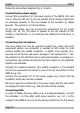
7. Connecting the GBM-8
There are terminal strips soldered to the module´s connections, used to
plug in and screw on the connection cables.
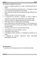
Each connection for the rails is internally connected to one output. Each
pair of connections for the rails is assigned to one connection for the
power supply.
Connections GBM-8Booster
section
Rail
section Power supply Rails Output
1 G1 A1
1
2
V1a and V1b
G2 A2
3 G3 A3
2
4
V2a and V2b
G4 A4
5 G5 A5
3
6
V3a and V3b
G6 A6
7 G7 A7
4
8
V4a and V4b
G8 A8
!