
User manual

English GBM-8
Page 34
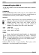
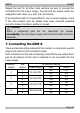
Follow the connections diagrams fig. 4, 5 and 6.
Connecting the power supply
Connect the connections for the power supply of the GBM-8 (V1a and
V1b or V2a and V2b etc.) to the rail outputs of the driving transformer
(in analogue layouts) or the rail outputs of the boosters (in digital
layouts). The polarity is not of importance.
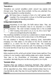
As the need arises, you can connect the connections for the power
supply (V1, V2, V3, V4) either in parallel to the rail outputs of one
booster or transformer or to maximum four different transformers or
boosters.
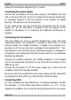
Connecting the rail sections
The busy status can only be reported trouble free, when with each
supervised section one conductor is isolated at both ends. In 3-rail
systems isolate the middle conductor, in digital 2-rail systems (d.c.
layouts) one of the two rails and in analogue 2-rail systems the "-" rail.
Pay attention to the fact that, due to technical principles, in analogue 2-
rail systems only vehicles driving into the track section in one particular
direction are detected.
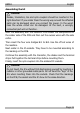
Connect the isolated conductor (the middle conductor or the isolated
rail) of the supervised rail section to one of the rail connections of the
GBM-8 (e.g. G1).
Connect the connection "a" for the power supply (e.g. V1a) to the rail
conductor which has not been isolated.
Be sure to use the connections for the power supply and the rails which
are assigned to each other (e.g. V3a and V3b and G5 and G6).
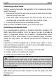
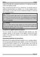
Connecting LEDs
In order to display the busy status (e.g. in analogue displays), connect
the cathodes (-) of the LEDs (with series resistors, e.g. 1 K) to the
outputs of the GBM-8. Do not use the driving transformer for the power