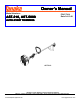
Owner’ s Man ual Owner’s Manual Model Numbers: P/N 27344 Date 04-19-01 AST-210, AST-5000 AUT O-ST AR T TRIMMERS UTO-ST O-STAR ART AST-210 Supplier To The Outdoor Power Equipment Industry ISM, Inc. • 1028 4th Street SW • Auburn, WA 98001 • Phone: (253) 333-1200 • Fax: (253) 333-1212 www.tanakapowerequipment.com custsvc@tanaka-ism.
AST-210,AST-5000 Owner’s Manual Before using this unit: • • • Read the operator’s manual carefully. Check that the cutting equipment is correctly assembled and adjusted. Start the unit and check the carburetor adjustment. See “Maintenance”. WARNING The engine exhaust from this product contains chemicals known to the State of California to cause cancer, birth defects and other reproductive harm. Always wear eye, head and ear protectors when using this unit.
AST-210,AST-5000 Be careful of thrown objects. Gloves should be worn when necessary, e.g. when assembling cutting equipment. Blade thrust may occur when the spinning blade contacts a solid object in the critical area. A dangerous reaction may occur causing the entire unit and operator to be thrust violently. This reaction is called BLADE THRUST. As a result, the operator may lose control of the unit which may cause serious or fatal injury.
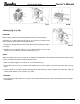
AST-210,AST-5000 Owner’s Manual 1. What is what ? Since this manual covers several models, there may be some difference between pictures and your unit. Use the instructions that apply to your unit. www.tanakapowerequipment.com 3 custsvc@tanaka-ism.
AST-210,AST-5000 Owner’s Manual • 2. Warnings and safety instructions. • • • • Operator Safety • Always wear a safety face shield or goggles. • Always wear heavy, long pants, boots and gloves. Do not wear loose clothing, jewelry, short pants, sandals or go barefoot. Secure hair so it is above shoulder length. • Do not operate that tool when you are tired, ill or under the influence of alcohol, drugs or medication. • Never let a child or inexperienced person operate the machine.
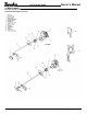
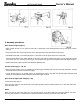
AST-210,AST-5000 Owner’s Manual 3. Assembly procedures Drive shaft to engine (Fig.1-1) • Apply a small amount of oil or grease to insert part of shaft tube, loosen shaft tightening bolt (1) and remove location bolts (4). • Insert the throttle wire (3) through the hole of the shaft grip and connect the electrical coupling (2). • Pull flexible inner shaft out of shaft tube about 3 " and insert it into the square hole in the clutch shaft.
AST-210,AST-5000 Owner’s Manual Installation of handle (Fig. 1-2, 2B) Attach the handle to the drive shaft tube with the angle towards the engine. Adjust the location to the most comfortable position before operation. Remove the handle bracket (1) from the assembly. (Fig. 1 -3) Place the handles and attach the handle bracket with four bolts lightly. Adjust to appropriate position. Then fix it firmly with the bolts. Throttle wire/stop cord (AST-210) Connect stop cord connectors. (Fig.
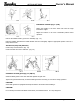
AST-210,AST-5000 Owner’s Manual When using a trimmer head (2) with two-piece type blade guard, attach the guard extension to the blade guard. (Fig. 1-7) Then locate the guard above the angle transmission. (Fig. 1-7B) NOTE! If your unit has guard location label on drive shaft tube, follow the indication. NOTE! To remove the guard extension, refer to the drawings. Wear gloves as the extension has a sharp line limiter, then push the four square tabs on the guard one by one in order. (Fig.
AST-210,AST-5000 Owner’s Manual 4. Operating procedures Fuel (Fig. 2-1) WARNING! The trimmer is equipped with a two-stroke engine. Always run the engine on fuel, which is mixed with oil. Provide good ventilation, when fueling or handling fuel. Fuel • Always use branded 89 octane unleaded gasoline. • Use Tanaka two-cycle oil or a quality two-cycle oil at mixing ratio of 25-50:1 (Gasoline (A) : Oil (B)), only for the state of California at 50:1. • Never use multi-grade oil (10 W/30) or waste oil.
AST-210,AST-5000 Owner’s Manual Starting (Fig. 2-2, 2B) CAUTION! Before starting, make sure the cutting attachment does not touch anything. The battery is not fully charged at the factory. It is necessary to charge it fully before operation. Please follow "Charging Procedures". 1 .Depress the priming bulb (3) several times until fuel flows through the bulb or return pipe. 2. Depress the fuel injection button (4) once which transfers fuel from the carburetor to the combustion chamber. (AST-250) (Fig.
AST-210,AST-5000 Owner’s Manual If the engine does not start: 1. If the engine starts but does not continue to run, repeat steps 1 to 5. 2. If the starter does not make any noise, repeat the charging procedures. (Optional)(AST-250) 3. To start the unit with the recoil starter, if so equipped, follow starting procedures number 1 and turn the switch to the "On" position then pull the recoil starter handle briskly. (Fig. 2-2D) Stopping (Fig. 2-2B) Decrease engine speed, set ignition switch to (OFF) position.
AST-210,AST-5000 Owner’s Manual Cutting (Fig. 2-4, 4B, 4C, 4D) • When cutting, operate engine at over 6500 rpm. Extended use at a slow speeds may wear the clutch prematurely. • Cut grass from right to left. • Blade thrust may occur when the spinning blade contacts a solid object in the critical area. A dangerous reaction may occur causing the entire unit and operator to be thrust violently. This reaction is called BLADE THRUST.
AST-210,AST-5000 Owner’s Manual 5. Maintenance MAINTENANCE, REPLACEMENT, OR REPAIR OF THE EMISSION CONTROL DEVICES AND SYSTEMS MAY BE PERFORMED BY ANY NONROAD ENGINE REPAIR ESTABLISHMENT OR INDIVIDUAL. Carburetor adjustment (Fig. 3-1, 1B) WARNING! The cutting attachment may be spinning during carburetor adjustments. WARNING! Never start the engine without the complete clutch cover and tube assembled! Otherwise the clutch can come loose and cause personal injuries.
AST-210,AST-5000 Owner’s Manual Fuel Filter (Fig. 3-2B) Drain all fuel from fuel tank and pull fuel filter line from tank. Pull filter element out of holder assembly and rinse element in warm water with detergent. Rinse thoroughly until all traces of detergent are eliminated. Squeeze, do not wring, away excess water and allow element to air dry. NOTE! If element is hard due to excessive dirt buildup, replace it. Spark plug (Fig.
AST-210,AST-5000 Owner’s Manual Flexible drive shaft (Fig. 3-5) Flexible drive shaft should be removed and lubricated with a good quality lithium grease every 20 hours. To remove the flexible shaft, first remove screw (1), loosen bolt (2) and remove the gear case then pull the shaft out of the drive shaft pipe.
AST-210,AST-5000 Owner’s Manual Battery Removal (AST-5000) 1.Separate drive shaft from engine and throttle wire (1) from throttle trigger. Disconnect couplers (2). (Fig. 3-7) 2. Remove four screws (4), which are retaining fan case cover (3). (Fig. 3-8) 3. Bind the female coupler with long nose pliers and push it to separate the coupler from fan case cover (3). (Fig. 3-9) 4. After removing the fan case cover, pull out the battery with the waterproof cover (1). (Fig. 3-10) 5.
AST-210,AST-5000 Owner’s Manual Maintenance schedule Below you will find some general maintenance instructions. For further information please contact your Tanaka service dealer. Daily maintenance • Clean the exterior of the unit. • Check that the harness is undamaged. • Check the blade guard for damage or cracks. Change the guard in case of impacts or cracks. • Make sure the cutting attachment is properly centered, sharp, and without cracks.
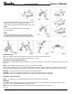
AST-210,AST-5000 Owner’s Manual 6. Optional Installation of free disk set (optional) (Fig. 4-1, 1 B) 1) Disassemble free disk (7) from the free disk set by loosening three bolts (8). 2) Place blade (3) as shown in drawing. Disk fixing bolt (4) is left-hand threaded ' Use special care to fix blade firmly. Use alien wrench (1) to hold cutter holder (2) so that you may easily tighten up disk fixing bolt (4) with wrench (6).
AST-210,AST-5000 Owner’s Manual 7. Specifications Note : Sound levels are calculated as the time-weighted energy total under various working conditions with the following time distribution : ½ idling, ½ racing. * All data subject to change without notice. www.tanakapowerequipment.com 18 custsvc@tanaka-ism.
AST-210,AST-5000 Owner’s Manual Declaration of conformity D6claration de conformit6 Dichiarazione di conformita Konformitiitserkliirung Declaraci6n de conformidad Konformitetsdeklaration We, Nous,soussignds, Noi, Der unterzelchnete, Nosotros, Tanaka Kogyo Co., Ltd.
AST-210,AST-5000 Owner’s Manual IMPORTANT NOTICE THIS INFORMATION IS FOR THE US AND CANADIAN MARKETS ONLY. • To reduce the risk of injury from loss of control, never use a metal blade on a curved shaft grass trimmer. • Never use a metal blade on any brushcutter without barrier bar or bicycle handle configuration and safety strap and approve guard. • Use only attachments or accessories designed for your unit.