SERVICE MANUAL GRASS TRIMMERS / BRUSH CUTTERS • TROUBLE SHOOTING • SERVICE / TORQUE LIMITS • TECHNICAL DATA 1028 4th Street S.W. • Building B • Auburn, WA 98001 • PH: 253-333-1200 • F: 253-333-1212 • tanakapowerequipment.
Introduction How To Use Your Service Manual Replacement Parts This Service Manual is arranged for quick, easy reference When replacement parts are required, use only approved and is divided into numbered sections. parts. Failure to do somayresult in products malfunction and possible injury to operator and/or bystander. NOTE : Read all information for servicing a part or system before repair work is started to avoid needless assembly.
Safety Alert Symbol and Notations The following safety notations are used throughout this manual to call attention to special information or operating procedures. Understand the message in each notation and be alert to unsafe conditions and the possibility of personal injury. NOTE: A NOTE points out general reference information regarding proper operation and maintenance practices.
CONTENTS 1. Special tools page 1 2. Technical Data 2 3. Service Limits 4 4. Torque Limits 5 5. General Components & Inspections 1. Crankcase 2. Cylinder 3. Piston 4. Piston pin bore 5. Piston ring end gap 6. Piston ring side clearance 7. Piston pin 8. Crankshaft journal 9. Connecting rod/big end side clearance 10. Eccentricity of crank shaft 11. Centrifugal clutch 12. Spark plug 13. Ignition coil inspection 14. Inspection of cylinder compression 15. Tank cap 6 6 6 6 6 6 7 7 7 7 7 7 8 8 8 9 6.
1. Special Tool List Ref.
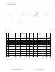
2. Technical Data Model Displacement (cc) Bore x Stroke (mm) Compression ratio Max. kW/rpm Max. kg Em/rpm Max. rpm Idling rpm Clutch-meet rpm Carburetor (maker/type ) Fixed Jet (main jet #) L/H needle set Metering lever height (mm) Ignition system Air gap (mm) Ignition timing ( K) Spark plug(maker) Gap (mm) Clutch drum diameter (mm) Gear Ratio Model Displacement (cc) Bore x Stroke (mm) Compression ratio Max. PS/rpm Max. kW/rpm Max. kg Em/rpm Max.
2. Technical Data Model Displacement (cc) Bore x Stroke (mm) Compression ratio Max. PS/rpm Max. kW/rpm Max. kg m/rpm Max. rpm Idling rpm Clutch-meet rpm Carburetor (maker/type) Fixed Jet (main jet #) L/H needle set Metering lever height (mm) Ignition system Air gap (mm) Ignition timing ( ) Spark plug(maker) Gap (mm) Clutch drum Diameter (mm) Gear Ratio TBC-420PF 430PF series TBC-550 series TBC-600 46.5 43 x 32 7.0 : 1 2.38/7000 1.75/7000 0.26/6000 11500 2800±200 3800±200 HDA180 N/A 90 46.5 43 x 32 7.
3. Service Limit CYLINDER BORE PISTON / SKIRT OUTER DIA. PISTON PIN BORE PISTON PIN OUTER DIA. CON-ROD BIG END SIDE CLEARANCE CON-ROD SMALL END SIDE CLEARANCE CRANKSHAFT ECCENTRICITY CRANKSHAFT JOURNAL DIA. (PTO) CRANKSHAFT JOURNAL DIA. (STARTER) CLUTCH DRUM INNER DIA. CLUTCH DRUM SHAFT DIA. For ALL MODELS MODEL MAX. MIN. MAX. MIN. MAX. MAX. MAX. MIN. MIN. MAX. MIN. TBC-230B series 31.04 30.80 8.05 7.96 0.50 - 0.10 11.90 11.90 55.00 11.95 TBC-230 series 31.04 30.80 8.
4. Torque Limits SPECIAL FASTENERS Reference kg-cm In-lb Flywheel nut 200 - 230 173.6 - 199.6 Clutch or Special nut Spark plug Carb. insulator 200 - 250 150 - 200 50 - 60 173.6 - 217.0 130.2 - 173.6 43.4 - 52.1 CyIinder 45 - 50 39.1 - 43.4 Crankcase 40 - 50 34.7 - 43.4 ORDINARY NUTS AND BOLTS Reference kg-cm In-lb M4 Screw M5 Screw 20 - 30 40 - 50 17.3 - 26.0 34.7 - 43.4 M6 Screw M4 Nut M5 Nut 60 - 70 20 - 30 40 - 50 52.1 - 60 7 17.3 - 26.0 34.7 - 43.
Sealing is essential. Fig. 1 WWW.TANAKAPOWEREQUIPMENT.COM 6 CUSTSVC@NIKKO-TANAKA-USA.
WWW.TANAKAPOWEREQUIPMENT.COM 7 CUSTSVC@NIKKO-TANAKA-USA.
WWW.TANAKAPOWEREQUIPMENT.COM 8 CUSTSVC@NIKKO-TANAKA-USA.
WWW.TANAKAPOWEREQUIPMENT.COM 9 CUSTSVC@NIKKO-TANAKA-USA.
6. ENGINE SIDE 6-1 Recoil Starter System NOTE: Never disassemble Spring Case Assy. You may get hurt. 1) Remove recoil starter body assy from unit. 2) Pull starter handle, then hold rope reel and pull starter rope out from ropoe reel. Fig. 15 3) While holding rope reel, let recoil spring unwind slowly. Then remove the holding screw from the center of the recoil body Fig. 16 6) Check for wear and/or damage to the starter pawl and spring on the starter pulley and replace as necessary. Fig.
Needle Pin WWW.TANAKAPOWEREQUIPMENT.COM 11 CUSTSVC@NIKKO-TANAKA-USA.
C. To maintain carburetor performance, it is recommended that rubber parts be inspected periodically or whenever disassembled. Check diaphragm for deterioration or damage, valve hinge for deformation and needle valve for wear. Always use fresh fuel. Fuel which has been stored for an extended periods of time will damage carburetor parts and decrease performance. NOTE: Make sure not to damage the end of the crankshaft, when removing the magneto rotor.
4) Remove the screws securing cylinder and pull cylinder off of the crankcase, before installing cylinder apply a thin coat of oil to the piston. B. Apply a coat of grease to the lip of each oil seal, then install shims on the starter side of the crankshaft and insert crankshaft into the crankcase. Align each piston ring with the locator pin, slowly insert piston into cylinder while compressing the rings in with your fingers.
WWW.TANAKAPOWEREQUIPMENT.COM 14 CUSTSVC@NIKKO-TANAKA-USA.
7. DRIVE SIDE 7-1 Removing and assembling clutch drum 1) Remove stop ring from clutch drum using long nose snap ring pliers. Fig.33 2) Then remove clutch drum from fan case or clutch case using handle bar 8x120 from the stop ring side. 3) Some ball bearing holding clutch drums can be removed from fan case or clutch case using the snap ring pliers after removing clutch drum. NOTE: Check for any wearing of the inner diameter of clutch drum and /or splines and/or any other parts and replace as necessary.
7- 4 Assembling gear case 1) Install ball bearing into the bottom of gear case using the proper daimeter installer. See below for diameters. Dia. 20mm ----- TBC-230 series Dia. 24mm ----- TBC-2501/250PF/260PF/270 series, TBC420PF TBC-4200D/DLV/430PFLV/550/600 2) Apply grease on gear shaft and insert it into ball bearing which was installed in section 1) using one of gear shaft inserter’s shown on the Special tool list. Fig.
4.
Power is low or poor Carbon deposits in muffler Poor cylinder pressure Dirty air cleaner element Incorrect carburetor adjustment Worn or damaged internal parts Runs inconstantly Bad spark plug Bad ignition coil Incorrect carburetor adjustment Engine doesn't run properly Air leak at intake Air leak from fuel pipe Lean carburetor adjustment Clogged fuel filter Doesn't accelerate Engine isn't warm enough, Warm up engine Lean carburetor adjustment Air leak at intake Air leak from pipe Clogged fuel filter