Codian HD MCU MCU 4500 Series Getting started
Codian MCU MCU 4500 Series Getting started
Copyright © Codian 2008. All rights reserved. This Getting Started Guide may not be copied, photocopied, translated, reproduced, or converted into any electronic or machine-readable form in whole or in part without prior written approval of Codian Limited. Codian Limited reserves the right to revise this documentation and to make changes in content from time to time without obligation on the part of Codian Limited to provide notification of such revision or change.
Table of contents General information ................................................................................................................ 1 About the Multipoint Control Unit (MCU) ......................................................... 1 Package contents ........................................................................................................ 1 Port and LED location ................................................................................................ 1 LED behavior .
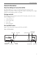
General information General information About the Multipoint Control Unit (MCU) The MCU 4500 Series is a range of technologically advanced and powerful Multipoint Control Units. They are designed to combine continuous presence at high definition and the highest possible voice quality. Package contents The following items are included with the MCU.
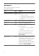
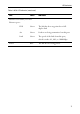
LED behavior Table 1 describes the behavior of the LEDs.
LED behavior Table 1: MCU LED behavior (continued) LED Color Indicates Ethernet Port Status, for each Ethernet port : Power FDX Green The link has been negotiated as a fullduplex link Act Green Packets are being transmitted on this port Link Green The speed of the link from this port, which is either 10, 100, or 1000 Mbps Blue The MCU is receiving power 3
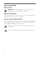
Connecting the MCU Before you start IMPORTANT: Before installing the MCU, you must read the safety information at http://www.codian.com/safety.htm Step one: Connect power Connect the power connector on the rear of the unit to the power supply using the supplied power cable. (There is no On/Off switch.) Step two: Connect to Ethernet Port A Connect an Ethernet cable from Ethernet Port A to an Ethernet switch (rather than a hub, to minimize interference from other devices on the network).
Initial configuration Initial configuration Step one: Connect to the console port 1 2 3 4 Ensure power is connected to the MCU and the Status LED is green. Connect the console port of the MCU to the serial port of your PC using the blue RJ45 to DB9 cable supplied. Use a serial terminal program, such as Secure CRT or HyperTerminal, to connect to the MCU.
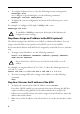
To configure Ethernet Port A, enter the following for auto-sensing mode: ethertype auto or to configure a speed and duplex, use the following command: ethertype <10|100> To display the current configuration and status of the Ethernet ports, enter: status For example, to configure a full-duplex 100Mbps link, enter: ethertype 100 full i To establish a 1000Mbps connection, both ends of the link must be configured as auto-sensing.
Configuring the MCU Configuring the MCU Step one: Log in to the MCU All administration of the MCU is performed via the web interface. To log in to the web interface of the MCU: 1 2 Use your browser to navigate to the IP address of the MCU (to discover the IP address, refer to the previous section). Click the Log in link on the top right of the screen, then click Change log in and enter the user name admin with no password.
Step three: Add endpoints (optional) One way to add participants to a conference that you create is to have the MCU automatically call them when the conference starts. To do this, you configure their endpoints on the MCU. When you set up a conference, you can choose the endpoints from the Pre-configured participants list. This is easier than entering each endpoint’s details every time. Participants that are pre-configured for a conference will automatically be called by the MCU to join that conference.
Using the MCU Using the MCU Creating conferences To create a conference: 1 2 3 In the web interface of the MCU, go to Conferences and click Add new conference. Type a Name for the conference, for example SalesMeeting. Type an optional numeric identifier, for example 123. This will be the telephone number that participants can use to join the conference when calling in to the MCU via a gatekeeper or SIP registrar. i 4 5 6 If you are using a gatekeeper, check H.
Calling participants in to a conference To call participants in to a conference: 1 2 3 4 5 In the web interface of the MCU, go to Conferences and click on the name of an active conference. On the Participants tab, click Add participant to call out to an H.323 or SIP endpoint. In the Address field: where there is no H.323 gatekeeper or SIP registrar, type the IP address, host name, or SIP URI of an accessible endpoint on your network if you are using an H.
Using the MCU Streaming conferences Streaming is a way of viewing a conference in a standard web browser. The MCU allows streaming of video and, if enabled for a conference, the streaming of data. You can also conduct a text ‘chat’ and add notes and drawings to the data stream. i Note that to use the ‘chat’ facility when streaming a conference, your MCU needs the web conferencing feature key. For more information, refer to your reseller.
Instructing conference participants You need to tell conference participants how to join conferences. You can also tell them how to use the Far-End Camera Controls (FECC) to navigate menus in the auto attendant and choose conference layouts. There is a document: Getting Started: Accessing Conferences available in the documentation area of the web site, which you can print out and give to conference participants.
Troubleshooting and technical support information Troubleshooting and technical support information Using the event log to help solve a problem Unless you are experiencing a problem, all event logging sources should be set to the default, which is Errors, warnings and information. For more information about configuring the event log, refer to the online help accessible from the web interface. You can use the event log to produce debugging information to assist technical support in solving your problem.
Technical specifications Power requirements Table 2: MCU ratings Rating Value Nominal voltage 115V to 230V 50/60 Hz Current rating 6A Maximum Supply voltage range 100 to 240V 50/60 Hz Over-current protection Ensure the supply to this unit is protected by a branch circuit protector rated by a maximum of 20A. ! Caution — over-current devices must meet applicable national and local electrical safety codes and be approved for the intended application.
61-0011-05