TANDBERG 3G Gateway User Manual Software version R1.0 D13841.
TANDBERG 3G Gateway User Manual Trademarks and copyright All rights reserved. This document contains information that is proprietary to TANDBERG. No part of this publication may be reproduced, stored in a retrieval system, or transmitted, in any form, or by any means, electronically, mechanically, by photocopying, or otherwise, without the prior written permission of TANDBERG.
TANDBERG 3G Gateway User Manual This document was written by the Research and Development Department of TANDBERG, Norway. We are committed to maintain a high level of quality in all our documentation. Towards this effort, we welcome you to Contact us with comments and suggestions regarding the content and structure of this document.
TANDBERG 3G Gateway User Manual Environmental Issues Thank you for buying a product which contributes to a reduction in pollution, and thereby helps save the environment. Our products reduce the need for travel and transport and thereby reduce pollution. Our products have either none or few consumable parts (chemicals, toner, gas, paper). Our products are low energy consuming products.
TANDBERG 3G Gateway User Manual Operator Safety Summary For your protection, please read these safety instructions completely before operating the equipment and keep this manual for future reference. The information in this summary is intended for operators. Carefully observe all warnings, precautions and instructions both on the apparatus and in the operating instructions. Warnings Caution risk of explosion if battery is replaced by an incorrect type.
TANDBERG 3G Gateway User Manual Contact us If you have any questions, comments or suggestions, please see the Online Support service at www.tandberg.net. It is also possible to send a fax or mail to the attention of: Product and Sales Support TANDBERG P.O.
1 Introduction Table of Contents 1 Introduction................................................................................................................................8 1.1 The TANDBERG 3G Gateway..............................................................................................10 1.1.1 3G GATEWAY Capacity – typical scenarios ............................................................11 2 Installation ...................................................................................
TANDBERG 3G Gateway User Manual 1 Introduction The TANDBERG 3G Gateway enables sites on IP and UMTS Handsets to participate in meetings with eachother with the quality and reliability found in all TANDBERG equipment.
1 Introduction algorithm, which is considered an adequate degree of encryption for commercial exchange Network and Features Up to 30 video sites can be connected at the same time Call rate of 64 Kbit on ISDN side and 109kbps on IP side for each call is supported through the 3G Gateway Video IVR Selecting IP endpoint from address book 9
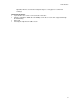
TANDBERG 3G Gateway User Manual 1.1 The TANDBERG 3G Gateway Front view The front panel provides 4 LAN interfaces, an LCD display, RS232 interface and control buttons. Rear view BRI interface PRI interface The back panel provides one PRI interface or 4 BRI interfaces depending on the configuration and one power switch/connector. Next to the PRI RJ-45 there are 4 LED’s. In normal working condition the green LED will be lit.
1 Introduction Red Alarm or Loss of signal (LOS) indicates that there is no signal and thus no framing info received. The same effect will be obtained by pulling out the PRI cable. This may also be caused by a broken connector in the receive (RX) part of the cable. Yellow Alarm or Remote Alarm Indicator (RAI) means that the 3G Gateway is receiving framing info, but in this framing info the other side tells the 3G Gateway that it is not reading the gateway’s transmitted framing info.
TANDBERG 3G Gateway User Manual 2 Installation Precautions: 12 Never install telephone wiring during a lightning storm. Never install telephone jacks in wet locations unless the jack is specifically designed for wet locations. Never touch uninstalled telephone wires or terminals unless the telephone line has been disconnected at the network interface. Use caution when installing or modifying telephone lines.
5 Configure the Gateway 2.1 Unpacking To avoid damage to the unit during transportation, the 3G Gateway is delivered in a special shipping box, which should contain the following components: User Manual and other documentation on CD. Rack-ears, screws and screwdriver.
TANDBERG 3G Gateway User Manual 2.2 Connecting cables Power cable Connect the system power cable to an electrical distribution socket. ISDN PRI or BRI cables The E1/T1 cable should be connected to a CSU (Channel Service Unit). You will need a CSU between your 3G Gateway and the PRI line from your network provider. LAN cable To use the 3G Gateway on IP, connect a LAN cable from the ‘LAN 1’ connector on the 3G Gateway to your network. The ‘LAN 2, 3 and 4’ connectors are not used and should be left open.
5 Configure the Gateway 2.3 3G Gateway Configuration The 3G Gateway requires some basic configurations before it can be used. It will be necessary to find the IP-address and to create the dial-in and dial-out services program the ISDN-PRI Line numbers. It is possible to use the front panel LCD display or the serial RS232 cable. Using the RS232 cable, follow the instructions below: 1. Connect the RS232 cable between the 3G Gateway and a PC and then switch on the 3G Gateway. 2.
TANDBERG 3G Gateway User Manual To configure the IP number follow the instructions below: 1. Press any key to get the main menu. 2. 3. 4. 5. 6. 7. 8. IP settings should be displayed. Press [ENTER] to access the IP settings menu. Us the [UP/DOWN] key to select IP Address. Press [ENTER] to access the IP address editing menu. Press [ENTER] again to get a cursor. Use up down keys to navigate between the different digits.
5 Configure the Gateway Note that the password can be changed in System Configuration’, Misc’. See also the section ‘5.5 Miscellaneous Configuration’.
TANDBERG 3G Gateway User Manual 3 Using the 3G Gateway 3.1 Call Overview The following Web-page, called ‘Overview’ will be shown when the correct password has been entered and shows all calls currently active through the 3G Gateway. GW Calls Shows each active call through the 3G Gateway. [Idle] No call is active. Active Call A call is active. Source / Destination Source shows the Status of the incoming call to the 3G Gateway, the number and which network the incoming call is using.
5 Configure the Gateway Destination shows the Status of the outgoing call from the 3G Gateway, the number and which network the outgoing call is using. Idle No active call, call has been disconnected. Alerting Call is being connected. Connected Call is connected. Establ out 3G Gateway is calling out to destination. Clear out Call is being disconnected. Number ISDN or IP number. IP/H.323 Call connected is using the H.323 protocol over IP. Duration Shows the length of the current call.
TANDBERG 3G Gateway User Manual 3.2 Dial from UMTS The gateway supports tree different UMTS Dial In services: - “DiD” “IVR” “Phonebook” Direct outwards dialing of a 3G handset. Dialing 3G terminals via selection menu. Selecting entry from gateway phonebook Any of these services can be enabled or disabled, but at least one must be enabled for incoming call routing to take place. In order to enable parallel incoming calls, a PRI number range must be defined.
5 Configure the Gateway Example: A videoconferencing system calls into the Extension Dial In number with IVR active. The gateway activates the ‘Welcome’ picture and sound. The videoconferencing system enters the extension (H.323 Alias) followed by the # (pound-sign) to indicate end of number. The gateway starts to call the IP endpoint and the “Connecting” picture and sound are activated. When the call is connected audio and video are transmitted through the gateway.
TANDBERG 3G Gateway User Manual Example: An UMTS phone calls into the Extension Dial In number with IVR phonebook active. The gateway shows a menu with makes it possible to submit the name (both Christian and first name) via the alphanumeric DTRMF keys . For example finding Michel is possible via pressing 6 (m,n,o),4 ,2. The top entry in the phonebook will be highlighted and pressing ‘#’ will starts to call the IP endpoint, the “Connecting” picture and sound are activated.
5 Configure the Gateway 3.3 Dial from IP IP endpoints and MCUs can call out through the gateway by using one of the services defined on the gateway. The gateway support three different dial out services: - “DiD” Direct outwards dialing of a 3G handset. - “IVR” Dialing 3G terminals via selection menu. - “Phonebook” Selecting entry from gateway phonebook Services Service prefixes are used for IP endpoints to access UMTS Handsets.
TANDBERG 3G Gateway User Manual For more details on H-323 Services, please see ‘5.7 Services’. Note that the bandwidth used for the call will be 109Kbit independent of the bandwidth selected on the IP endpoint, except for selecting 64 Kbit. However this will result in an audio only call.
5 Configure the Gateway 4 View System Status To view current gateway status, open ‘System Status’ as shown in the figure below.
TANDBERG 3G Gateway User Manual 4.1 PRI/BRI Status PRI Status The colored part of the system status indicates the condition of the ISDN PRI line. There are three possible conditions: Sync 30 of 30. ISDN layer 1 and 2 are up and in sync. Sync 0 of 0, ISDN layer 1 and 2 are in sync but not up. Red Alarm, 0 of 0, ISDN layer 1 and 2 are down, most time indicating a disconnected ISDN line.
5 Configure the Gateway BRI Status The picture below show the status page of a BRI version of the gateway The BRI status displays the conditions of ISDN layer 1 and 2 separately. Green indicates up and in sync. Red indicates not in sync and indicate probably a disconnected ISDN line. Besides the indications on the webpage each ISDN BRI interface located at the back-side of the 3G Gateway has a green and orange LED.
TANDBERG 3G Gateway User Manual Note that in case the BRI 3G gateway is connected with less then 4 BR lines the BRI interfaces with the highest number(s) should be left open. For example when only 2 ISDN lines are used they should be connected with interface 1 and 2.
5 Configure the Gateway 4.2 H.323 Status To view H.323 gatekeeper status, open ‘H.323 Status’ as shown in the figure below. Note that it is not possible to use this IP address to place calls through the Gateway. GW IP Address Shows the IP address of the gateway. H.323 Gatekeeper Status Shows status and IP address of the Gatekeeper, the gateway is registered to. ‘Inactive’ means the gateway is not registered to a gatekeeper.
TANDBERG 3G Gateway User Manual 4.3 System Information To view gateway information, open ‘System Information as shown in the figure below. This page provides information on installed software and hardware.
5 Configure the Gateway 4.4 Available Resources To view available resources on the gateway, open ‘Available Resources’ as shown in the figure below. The available resources shows the actual System Load, the amount of video calls and the amount of available ISDN channels. These figures depend on the usage of the system. Note that available SystemLoad 100% indicates no load on the gateway.
TANDBERG 3G Gateway User Manual 5 Configure the Gateway To configure the gateway, open ‘System Configuration’ and ‘Gateway Configuration’. 32 System Configuration IP Configuration H.
5 Configure the Gateway 5.1 System Configuration 5.1.1 PRI Configuration To configure the PRI, select ‘System Configuration - PRI’ as shown in the figure below. PRI Protocol Select between the following PRI protocols: ETSI (Euro ISDN) National ISDN AT&T Custom Save When all settings are entered, please press the ‘Save’ - button to store the new settings. Note changing from E1 to T1 configuration requires a restart of the unit.
TANDBERG 3G Gateway User Manual Interface Configuration This section configures the PRI or ISDN interface. PRI CRC-4 Used for most E1-PRI configurations. If your network equipment does not support this feature, set PRI CRC-4 to Off. Bearer capabilities Within ISDN different bearer capabilities are used to signal the type of date (Voice, Data, H320, H324M), which is used by switches and other equipment to determine what to do with the data or the call (compressing voice data neglect etc).
5 Configure the Gateway 5.1.2 BRI configuration To configure the 4 BRI ports, select ‘System Configuration - BRI’ as shown in the figure below. BRI Protocol Select between the following BRI protocols: ETSI (Euro ISDN) National ISDN AT&T Custom Bearer capabilities Within ISDN different bearer capabilities are used to signal the type of date (Voice, Data, H320, H324M), which is used by switches and other equipment to determine what to do with the data or the call (compressing voice data, neglect etc).
TANDBERG 3G Gateway User Manual o UDI: In some situations the switch does not accept calls which use the correct H324M capability. This setting makes it possible to use the gateway in these situations via selecting UDI. Note that it is not possible to configure ISDN BRI lines for special functions like dial out only. The gateway will automatically select a free BRI line for H323 to 3G calls and possibly block a DiD or an IVR menu when the BRI lines have different numbers.
5 Configure the Gateway 5.2 IP Configuration To configure the IP settings on the gateway, open ‘System Configuration - IP’ as shown in the figure below. Configuration IP Address Assignment DHCP: Dynamic Host Configuration Protocol can be selected when a DHCP server is present. Static IP Address, Static IP Subnet Mask and Static IP Gateway are ignored because these parameters are assigned by the DHCP server.
TANDBERG 3G Gateway User Manual IP Ethernet Speed Auto 10Half 10Full 100Half 100Full The gateway will automatically detect the speed/duplex on the LAN. The gateway will connect to the LAN using 10 Mbps/Half Duplex. The gateway will connect to the LAN using 10 Mbps/Full Duplex. The gateway will connect to the LAN using 100 Mbps/Half Duplex. The gateway will connect to the LAN using 100 Mbps/Full Duplex. Static IP Address The Static IP Address defines the network address of the gateway.
5 Configure the Gateway 5.3 H.323 Configuration To dial out from IP to ISDN, through the gateway, requires the use of H.323 numbers (E.164 aliases). This means that the gateway must be registered to a Gatekeeper. H.323 Gatekeeper Status shows the current status of the Gatekeeper registration. Note that if the Gatekeeper is configured with an alternative Gatekeeper, the Status area might report a registration to the IP address of the alternative Gatekeeper.
TANDBERG 3G Gateway User Manual Gatekeeper Settings Gatekeeper Mode Enables the gateway to register to a Gatekeeper or without (direct mode). Selecting direct will gray out the gatekeeper IP address settings. When registered with a gatekeeper, the H.323 Gatekeeper Status shows Registered, Gatekeeper’s IP address and what port used. Selecting direct mode will result in no Gatekeeper registration; hence it is not possible to dial through the Gateway via alias names. The H.
5 Configure the Gateway 5.4 SNMP Configuration SNMP (Simple Network Management Protocol) is used for monitoring and configuring different units in a network. The gateway’s SNMP Agent responds to requests from SNMP Managers (a PC program etc.). SNMP traps are generated by the agent to inform the manager about important events. Note that the SNMP Community name is case sensitive.
TANDBERG 3G Gateway User Manual Configuration SNMP Mode The SNMP operation modus can be set to: On, turnn SNMP on; Off, turn SNMP off; ReadOnly, Do not send SNMP information to the host.; Trapsonly, Only send SNMP information identified as TRAPS to the host. SNMP Community Name SNMP Community names are used to authenticate SNMP requests. SNMP requests must have this ‘password’ in order to receive a response from the SNMP agent in the gateway.
5 Configure the Gateway 5.5 Miscellaneous Configuration To configure the miscellaneous settings on the gateway, open ‘Misc’ as shown in the figure below. Configuration To change the system name of the gateway, enter the new system name in the ‘System Name’. Password To change the system password of the gateway, enter the new password in the ‘New Administrator Password’. To delete the existing password, select ‘Delete Password’.
TANDBERG 3G Gateway User Manual In addition, the SNMP Service Read Only/Traps Only will make it possible to read SNMP messages in addition to enable/disable SNMP. Save Press ‘Save’ and then the ‘Restart’.
5 Configure the Gateway 5.6 Software Upgrade Software upgrade is where new software to the gateway can be installed from. It also shows current software version and the gateway’s hardware serial number. Note that to upgrade the Gateway, a valid Release key and Software file is required. Contact your TANDBERG representative for more details. System Information Software Version Hardware Serial Number Installed Options Shows the currently installed Software version.
TANDBERG 3G Gateway User Manual Install Software Release Key 46 Enter the release key in the Key field and press ‘Install Software’. You will be presented with a new page where you select the software package file to upload.
5 Configure the Gateway 5.7 Services Configuration Dialing rules for both UMTS handsets and H323 endpoints are configured via the services menu. In the services menu the following services types are distinguished: “DiD” Direct inwards dialling H.323 endpoint or 3G terminal “IVR” Dialling H.323 endpoint/3G terminal via a selection menu “Phonebook” Dialling H.323 endpoint/3G terminal from the 3G gateway phone book Figure 1: Proposed configuration webpage for the dialing rules.
TANDBERG 3G Gateway User Manual The configuration should be read from left to right as subsequent actions taken after each otter: In Prefix/nr (remove) in Postfix(remove) Service type out Prefix/Nr (add) out Postfix (add). The in Prefix/Nr & Postfix set will be used for matching the incoming called number/address. The out Prefix/Nr & Postfix set will be used to construct the number/address that will be called (if applicable). Prefix/nr (from) In case a number matches this prefix it will be removed.
5 Configure the Gateway 5.7.1 IVR The gateway contains a so called interactive video and voice response system which makes it possible to select destinations from a phonebook. It is also possible to submit a number of an IP endpoint when the extension is known. The figure below shows an example of the input screen. The numbers typed will appear after +/- ½ a second on the screen. Pressing the # key after submitting the number will start the gateway connecting with the endpoint with the submitted number.
TANDBERG 3G Gateway User Manual 5.7.2 examples Below there are two examples of service configurations. Example 1: Number plan mapping Service type DiD Net type (from): H324m/3G From Prefix/Nr: 6789 From Postfix: Net type (to): H323 To Prefix/Nr: 5 To Postfix: When dialing the number 67890000 there will be a match with “0000” as the significant number. The H.323 number to call is: 50000 (construction: prefix + significant numbers + postfix).
6 Appendices Appendix 1: Declaration of Conformity Appendix 2: Using the front panel LCD keys 51
TANDBERG 3G Gateway User Manual Appendix 1: Declaration of Conformity Contact your TANDBERG representative for a Declaration of Conformity.
Appendix 2: using the front panel LCD keys Every button on the front panel has multiple functions due to the limited amount of keys. In this appendix it is explained what the different functions are at different levels.
TANDBERG 3G Gateway User Manual Up/Down: browse Yes/No ENTER: in No state: State 3 ENTER: in Yes state, store, State 2 ESC: Cancel the edit, State 2 State 6: "Confirm" Menu Items like State 1 with Yes/No, No is the default Up/Down: Scroll through Yes/No ENTER: Confirm choice, State 1 ESC: State 1 State . 54 7: Choose Configuration option.